Ben Wood
-
Posts
133 -
Joined
-
Last visited
-
Days Won
1
Content Type
Profiles
Forums
Downloads
Store
eMastercam Wiki
Blogs
Gallery
Events
Everything posted by Ben Wood
-
Is it possible its looking for pitch instead of ipm for the feedrate?
-
Why I have stuck with X7sp2
Ben Wood replied to Teh Bear without Brains kinda idiot's topic in Industrial Forum
With Windows its best to avoid every other version. 98 was better then ME XP was better then Vista 7 was better then 8 -
I thought in the older versions you had to program from top WCS for 5 axis paths. I could be wrong though since I never tried any other way.
-
Generic FANUC POST files for Mastercam x9
Ben Wood replied to wesright's topic in Post Processor Development Forum
If you are going to continue using Mastercam I would recommend going with 2017. If you are just starting out it won't make much difference which interface you learn. If you learn X9 then later update to 2017 or later version it will be frustrating learning were everything is in the new interface. -
Generic FANUC POST files for Mastercam x9
Ben Wood replied to wesright's topic in Post Processor Development Forum
I used to work at a shop that had a Fanuc wire and Surfcam. Its been at least 8 years. Back then we were told that PC FaptCut was the only software that would output the power settings. I don't know if that was correct or if it has changed. We didn't have the PC FaptCut software. We were able to output the g code path out of Surfcam. On the control we could select the material, thickness, and number of passes and have it create a main program that would call the Surfcam generated code as a subprogram. It worked pretty good but it would have been nice to be able to do it all from the CAM software. I don't run wire machines anymore but the shop I'm at now the wire guys program Agie and Charmilles with Mastercam. Sounds like they are using about the same method. I think Mastercam has the ability but they seem to think what they are doing is easier. Might be because there posts need some work. -
I would also recommend turning off adaptive quality. There are a few other ways to increase the precision of verify that seem to work better. First is to check the box in simulation options for always use 5 axis mode. If you have 3 axis programs this will increase the precision. If they are 5 axis programs it is already using it so it won't make a difference. The other option is to open the MastercamSimulatorDefaults.xml file in the my macam2017 folder. Find the line <PrecisionFactor>1</PrecisionFactor> and change the value to a higher number. Both methods work but add time to the verification. Going too high on the PrecisionFactor number really takes a long time.
-
When I started I had a very limited knowledge of the "Basic" computer programing language and a little graphing calculator programing experience. Between looking for examples in existing posts and reading on this site I was able to get to the point were I can handle most of the edits I need. It can be very frustrating at first. My post editing results in a lot of trial and error. Make sure you have a backup of your post and thoroughly test any changes you make. I have sometimes fixed one problem only to break something somewhere else. Sometime I don't even find the new problem until I use a tool path I don't normally use months later. I now keep a backup and a note with each change I make in case I have a problem later on. Without this site I couldn't have done half of what I have done. Most edits people need have been discussed on here already or something similar that might point you in the right direction. I still have a long way to go to do some of the stuff guys on here talk about. I try to read through most of the topics because I never know when I will learn something new.
-
To the best of my knowledge the following is correct. But I'm no expert either so I could be wrong. A * in front of a variable forces it to output the value. If you have a variable called test and put it on three lines in a row without the * it will only output the value once. If you put a * in front of it ( *test ) it would output it three times. If the variable has a $ on the end it means it is a system variable instead of one created by the post writer. I too would recommend getting the MP_Documentation portfolio from your reseller. I unfortunately didn't have it when I started. Now that I have it I see it would have saved me a lot of time and trouble in the beginning. I learned most of what I know from looking through the post for similar code, trial and error, and searching through emastercam. There is a ton of information on this website. A lot of the post edits I have done I couldn't have done without the information I got from emastercam.
-
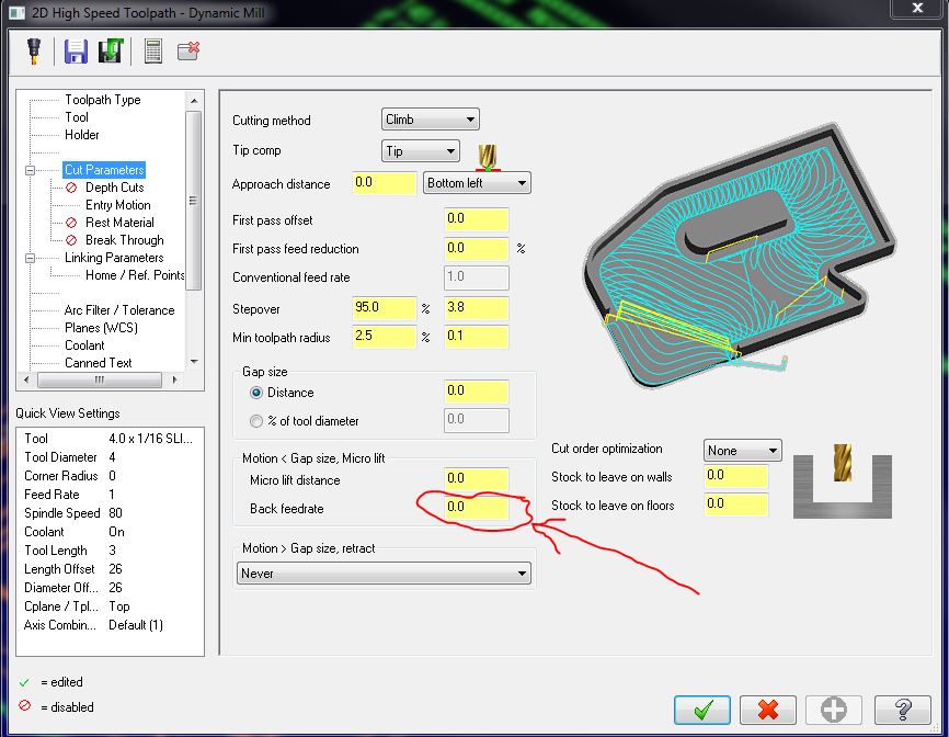
I've never had a problem with it. The feedrate your seeing isn't the back feedrate is it?
-
Programmable Stop Help Please
Ben Wood replied to volsfan's topic in Post Processor Development Forum
I could be wrong but I believe nextdc$ is a system variable and even if you don't currently have it in your post you can use it.- 26 replies
-
- 1
-

-
- programable stop
- post processor
- (and 1 more)
-
It has been discussed a few times before. There might be something in here that will help http://www.emastercam.com/board/topic/66485-autor-cursor/
-
I've had issues with project not working that were fixed by rebooting the computer.
-
I found some code using TCP for our Kitamura 5 axis with a Fanuc 16i-mb control. I see in this program I was using G05 P10000. T10 M06 (3MM BALL END MILL) G54 G17 G90 G40 G49 G80 G990 Q0 M69 (UNLOCK A) M11 (UNLOCK C) G00 A0. C0. G00 X-.3074 Y1.9288 S6500 M03 G43.4 H10 Z9.6187 M08 A-79.138 C24.124 G94 G05 P10000 X.4552 Y.2258 Z9.2606 G01 X.5552 F10. G00 X-.4476 X.0713 Y1.4014 Z9.7869 G49 G05 P0 M09 M05 G91 G28 Z0. M01
-
I use TCP on a five axis and it seems to work pretty good. Most or all high speed code would give me an error when I tried using them with TCP. I've given up on even trying. Below are some links talking about the high speed codes. I too was thinking I had seen a post on this site discussing them but I couldn't find it in my bookmarks. http://www.cnczone.com/forums/fanuc/38604-hsm-functions-aicc-ai-nano-hpcc-risc.html http://www.practicalmachinist.com/vb/cnc-machining/ai-nano-high-precision-contour-control-201189/ http://www.practicalmachinist.com/vb/cnc-machining/fanuc-hsm-g08-g05-1-settings-171099/ http://www.mtbtech.net/blog/2012/11/09/FANUC-AI-High-Speed-Modes-Simplified.aspx
-
G95 output for tapping
Ben Wood replied to So not a Guru's topic in Post Processor Development Forum
It wasn't intentional. Not sure how it happened since I used copy and paste. I went back and fixed it in case someone else tries to use it. -
There may be better ways but here is how I did it in my post. Near the beginning of the post were the variables are initialized I created a new one. You can name the variable something else if it makes more sense to you. test1 : 0 At the beginning of the pretract post block I added if test1 = 1, "G94", test1 = 0, e$ In the ptap post block I added test1 = 1
-
G95 output for tapping
Ben Wood replied to So not a Guru's topic in Post Processor Development Forum
I am no expert but looking at the router post I modified I think you will have to make changes in three places. Below are the three areas with what I think needs to be changed. I am not sure what the !feed does but it was in my post so it may or may not be needed. If you want to control it by the misc values there will be a little more required to make it work. # General Output Settings # -------------------------------------------------------------------------- use_pitch : 1 #0 = Use feed for tapping, 1 = Use pitch for tapping <------------------------- Add this line # -------------------------------------------------------------------------- fmt "Q" 2 peck1$ #First peck increment (positive) fmt "Q" 2 shftdrl$ #Fine bore tool shift fmt "R" 2 refht_a #Reference height fmt "R" 2 refht_i #Reference height fmt "F" 2 pitch #Tap pitch (inches per thread) <------------------------------------------------------------------- Add this line fmt "N" 4 n_tap_thds$ #Number of threads per inch (tpi) / Pitch (mm) <---------------------------------------- Add this line ptap$ #Canned Tap Cycle pdrlcommonb if use_pitch = 0, <------------------------------------------------------------------------------------------------- Add this line [ <------------------------------------------------------------------------------------------------- Add this line result = newfs(17, feed) # Set for tapping Feedrate format pcan1, pbld, n$, *sgplane, *sgdrlref, *sgdrill, prdrlout, prdrlout, *feed, strcantext, e$ ] <------------------------------------------------------------------------------------------------- Add this line else, <------------------------------------------------------------------------------------------------- Add this line [ <------------------------------------------------------------------------------------------------- Add this line if met_tool$, pitch = n_tap_thds$ # Tap pitch (mm per thread) <----------------------- Add this line else, pitch = 1/n_tap_thds$ # Tap pitch (inches per thread) <----------------------- Add this line pcan1, pbld, n$, *sgplane, *sgdrlref, *sgdrill, prdrlout, <----------------------- Add this line prdrlout, *pitch, !feed, strcantext, e$ <---------------------------------------- Add this line ] <------------------------------------------------------------------------------------------------- Add this line pcom_movea # -------------------------------------------------------------------------- -
My best guess would be it stands for Mastercam post.
-
Noob help editing generic post
Ben Wood replied to BNFab's topic in Post Processor Development Forum
How did you make the change to the control definition? If you made the change through the operation manager by clicking file then edit it will only save it for that file. To make a global change to the control def you will have to make the change through settings. Not sure if all these steps are necessary but I first select design as the machine type then click new file. The I click settings then machine definition manager. Once in the machine def. manager I click the button to enter the control def. manager. I make my changes then hit the save button. Then I exit the control def manager to go back to the machine def. manager were I also click save and then exit. Then any new file you start will use the new control def. If you have an existing file you will have to reload the machine def. for the changes to take affect. -
Operations manager un-docked, strange maximize
Ben Wood replied to r6z4o6's topic in Industrial Forum
When I single click nothing happens. Double click and it maximizes and docks. -
I'm not a expert so make sure you have a backup before editing. I believe there are two places you will have to make a change. In the ptlchg_com post block change pbld, n$, "G43", *tlngno$, pfzout, scoolant, next_tool$, e$ to pbld, n$, "G43", *tlngno$, pfzout, next_tool$, e$ "/", scoolant, e$ and in the ptlchg0$ post block change pbld, n$, "G43", *tlngno$, pfzout, scoolant, e$ to pbld, n$, "G43", *tlngno$, pfzout, e$ "/", scoolant, e$
-
HOME POSITION ONLY ON END OF PROGRAM
Ben Wood replied to mirek1017's topic in Post Processor Development Forum
The following example would be how to change the Haas 3 axis post that ships with Mastercam. Yours should be similar. peof$ #End of file for non-zero tool pretract comment$ if stagetool = 1 & stagetltype = 2, pbld, n$, *first_tool$, e$ uninhibit_eof_probe$ n$, "G91G28Z0", e$ <--------------------ADD THIS LINE n$, "G28Y0", e$ <--------------------ADD THIS LINE n$, "M30", e$ -
Not 100% sure if this will work but you could give it a try. Create a variable called something like mstop1 and format it to 0. In the beginning of the plinout post block add if mstop1 = 1, "M00", e$ mstop1 = 0. At the beginning of the pcirout post block add if mstop1 = 0, "M00", e$ mstop1 = 1
-
If I am understanding correctly you want it to output when the pcout is called from within the plinout post block but not at any other time. If that is what you are trying to do I would created a new post block called something like pcout2 and change the pcout to pcout2 in the plinout post block. Have the new pcout2 post block look like the following. pcout2 #C axis output if index = zero & rot_on_x, [ if use_rotmcode & cabs <> prv_cabs, *sindx_mc if absinc$ = zero, "\ M80", "(", cabs, !cinc, "0" else, "\ M80", "(", cinc, !cabs, ")" ]