BSmith23
-
Posts
57 -
Joined
-
Last visited
Content Type
Profiles
Forums
Downloads
Store
eMastercam Wiki
Blogs
Gallery
Events
Everything posted by BSmith23
-
I think that after we accepted the quote from our Re-seller and issued a P.O., we had our new post within two weeks. They sent ours through Postability. And any changes that we have needed they have gotten fixed within a week. Good luck!
-
First, I am going to make a few assumptions, that you are using either Waterline, Scallop, Equal Scallop, Raster, or Hybrid. For this I would use Waterline or Scallop. Equal Scallop would be okay but takes a long time to process. I rarely use Hybrid. Next, make sure you are using a ballnose or bullnose endmill, depending on which tool path you use. If using Waterline, us a bullnose. If scallop, use a ballnose. Raster would be okay to with either tool. Do not use a Sharp Corner endmill! If using Waterline, check the Add cuts box on the Cut Parameters page, to add minimum stepdown and max stepover. If using Scallop, make sure Expand inside to out is checked on Cut Parameters page. When you verify, no matter what you do, it will look like there is steps. But the real look of the part may look nice and shiny. Just my thoughts. 100 ways to do most anything. Brent
-
Typically, I use a ball end mill, do a waterline toolpath first, then a scallop. Sometimes, depending on how much of the radius there is on the floor, you can get away with a scallop only. Typically when I use scallop like this, I will work outside to inside. But I also consider myself a newbie, even though I've been doing this almost 5 years now. And I know that Hybrid, and Equal Scallop will probably work well too. They take me longer to process. Brent
-
Just heard back from Curtiss Howard at CNC. He said that Waterline does not support undercut at all, which I didn't realize. He also mentioned Surface Contour, which I have plotted through and looks good. Also, while I was trying to figure this out, I found I could also use 2D Contour, with Depth Cuts, Tapered Walls, and Undercut all checked, and it seems to plot out correctly as well. But I will probably go with Surface Contour as my first option. Thanks gcode! Brent
-
I just posted this on Mastercam Forum, thought I would put it here too. I am trying to cut an 8' relief taper under a 90.16mm diameter bore. I am using a 3/4" slot mill with full 3mm radius and 1/2" shank. No matter what I select, it will only cut straight.it will not post any code that tapers out as the tool goes down. Anyone have any ideas? Mastercam 2019 file. Brent TAPER TEST.ZIP
-
Alt+E causing Mastercam 2020/2019 to stop working.
BSmith23 replied to SAJ2017's topic in Industrial Forum
I have not had any trouble with that on 2019. I haven't loaded 2020 yet. Brent -
Go here https://convertio.co/jpg-dxf/ Free to use.
-
The most reliable thing I've found when trying to do this, is to make sure the logo is black and white only. Something I've done also is convert the file to a .dxf file then bring it into Mastercam. It still may not be perfect, but if the original image is black and white only, it will come in a lot cleaner than if it's not. Hope this helps. Brent
-
I agree. I like working in it for some things, but have had good and bad luck with it. It is pretty vanilla I think, but I don't have anything to judge it against, so I guess I shouldn't. Brent
-
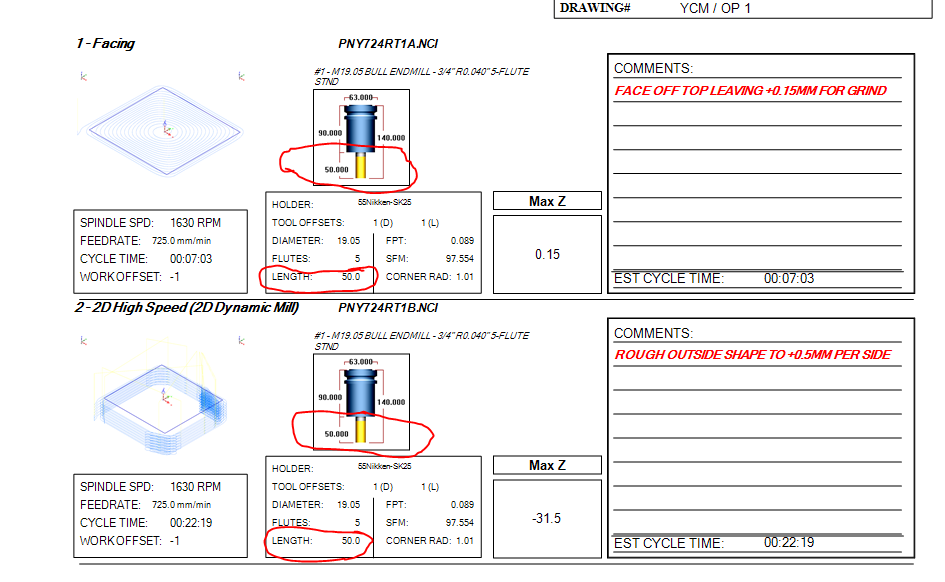
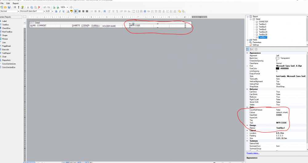
A coworker did before I got into the programming department. But I have tweaked it a few times to what you see here. It is similar to what the Active Reports Tutorial goes through. The Max Z is actually the lowest point the tool goes, not the highest. I could send you the files if you wish. Would just have to get our shop logo out of it, but that wouldn't take much. Brent
-
It doesn't on mine, just gives me the length from the holder. Brent
-
Try TOOL/OVERALL-LENGTH See if that works Brent
-
See if this helps. Like I say, they may have changed the field name for 2020, I don't know. I run into that with our other Set-up sheets whenever we upgrade, I usually have to change the Z value.

-
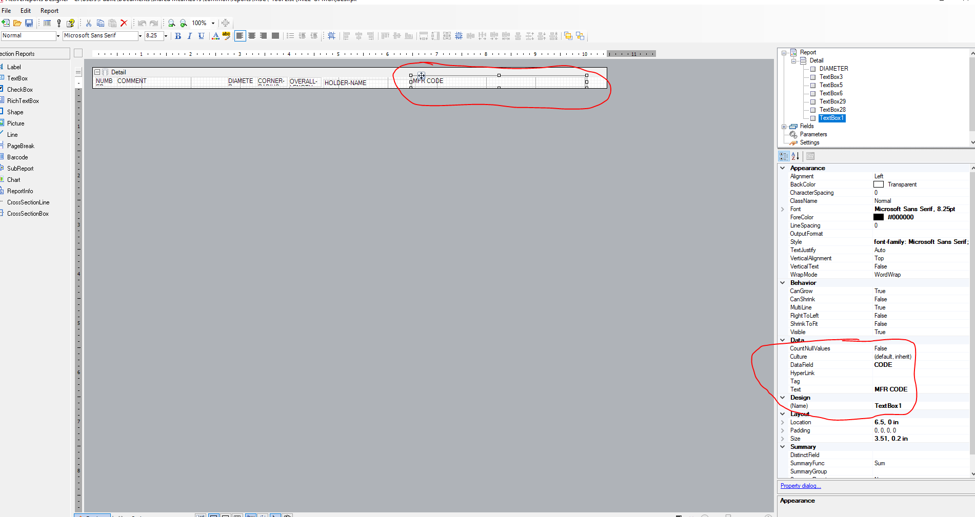
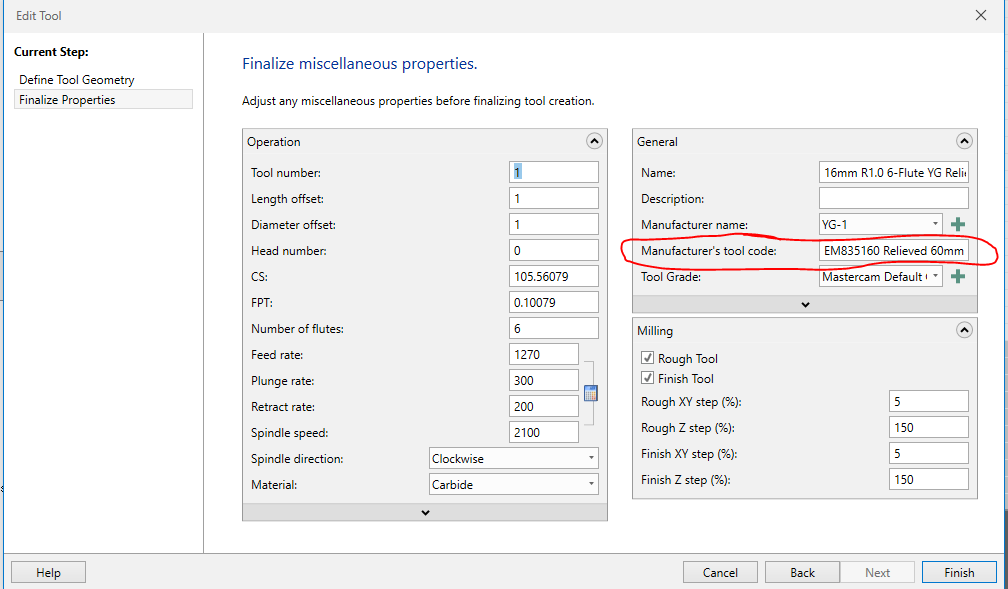
That's pretty close. Tool Crib # is where I put the EDP number at in the data field. Maybe 2020 has changed the list name for that data? I haven't upgraded yet, usually wait until at least one update has happened.
-
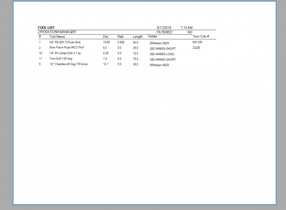
BLS is where the actual fields and field data is held. BLSPAGE is the main that references BLS to create the printed format. These are in 2019 format.
-
Does not have to be dxf file. can be x9 or dxf, and which way you do it makes a difference along which axis you draw your tool along and what levels are named what. I believe that an x9 file has to be drawn along the x-axis, and yes on center, with profile only, and level names don't matter. for the dxf however, go along the y-axis, and level one must be named CUT, and level 2 NOCUT, with cutting geometry on 1 and non-cutting geometry on 2. I may have those backwards, as I don't do it often, and I always have to go back to the Tool Manager tutorial to get it right. Someone here may be of more help than I. Brent
-
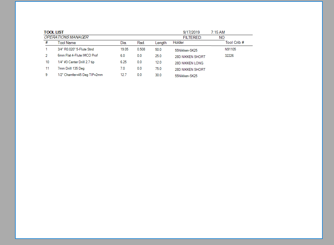
Yes you can. See if my files have what you are looking for. BLSPAGE is the headline and BLS is the tool list itself. Hopefully this helps. Brent -Tool List (MILL-OPMGR)BLS.rpx Tool List (MILL-OPMGR)BLSPAGE.rpx
-
I'm going to assume that before you start simulation, you have your WCS and workpiece oriented the way you will see it looking down from the Z-axis. If this is the case, depending on where your part x/y/z zero is, you may have to change Workpiece Position to "Translation in XYZ", and adjust those until you get the part where you want it. This is what I usually have to do to get it on my fixturing where I need it. Hope this helps. Brent
-
That's odd. It shows numbers for my 3d HS Toolpaths. And my 5-axis work too.
-
MIN-Z-TPLANE should do what you need. If not, there is a knowledge base article on Mastercam's website that should be able to help. Every time we've upgraded, I have had to search to find the right variable because it seems like it always changes. Hope this helps. Brent
-
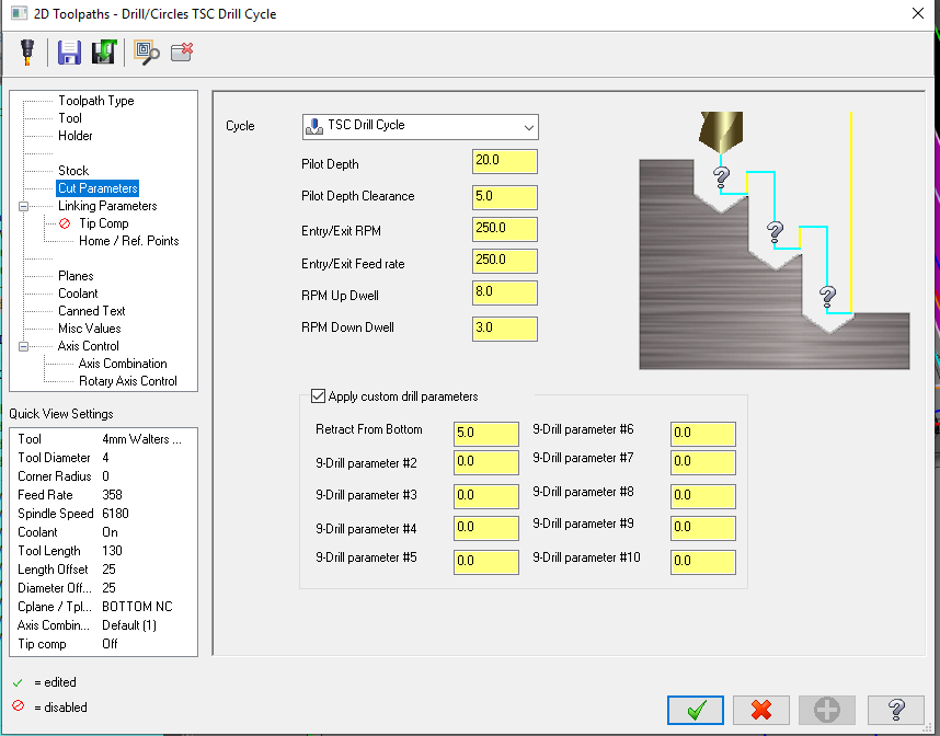
Our Reseller made us a Custom Drill Cycle exactly like this for our Fanuc controlled YCM's. We get really good code that we don't have to edit. We use Thru-Spindle Coolant drills with this cycle, and we don't turn on the thru-spindle coolant until after we get into the holes. Brent
-
I'm currently using a RTX-4000 with 2019 with no issues so far.
-
We got a DMG MORI 5-axis back in February, with a Heidenhain control. I have only ever use FANUC anywhere else I've worked, so it has been a bit of a learning curve for me too. There are some things I like about it, and others where I wish it was a FANUC. But overall, so far, not too bad.
-
Is there a way to set a default holders library for a certain Machine Definition? I have one machine that uses HSK63A holders, the rest use CAT/BT-40, so I want to set the HSK holders as default for that particular machine. Brent
-
setup sheets Active Reports Designer VS X+ for Setup Sheets
BSmith23 replied to Dave228's topic in Industrial Forum
Dave228, Those look nice. I thought ours looked good, but yours look pretty good too. Mine aren't quite as simple as yours are. Nice Job! Brent