All Activity
- Today
-
 thanha01 joined the community
 -

Integrating G234 in fanuc 5x generic post
Leon82 replied to ikertx0's topic in Post Processor Development Forum
that is usually in the locked section of the post. Nobody is goings to copy and paste it here. - Yesterday
-
 MILENKO110784 joined the community
 -

Looking for suggestions: MP pst file NC browser/viewer?
Craig-B replied to mavusi's topic in Post Processor Development Forum
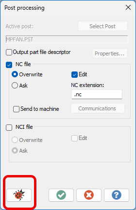
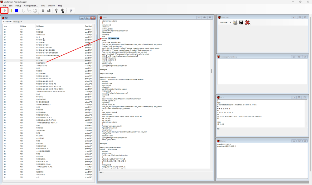
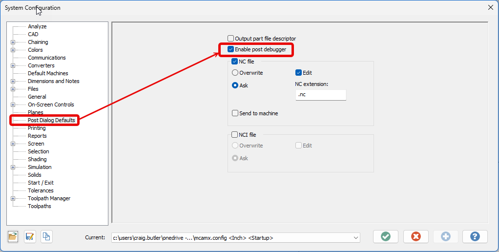
Hey Mavusi, They need to enable and use the post debugger. It will give you the ability to click on a G-code block in a .nc file and it will point you to the exact place in the .pst where that routine is defined. In the Mastercam configuration enable the post debugger. Instead of just posting run the debugger by selecting the bug When the debugger is launched press play run the file. In the NC window you will see the G-code if you double click the line of code it will show you where the code comes from in the post. Please note that if you have an encrypted post if will only show you the portion that is not encrypted.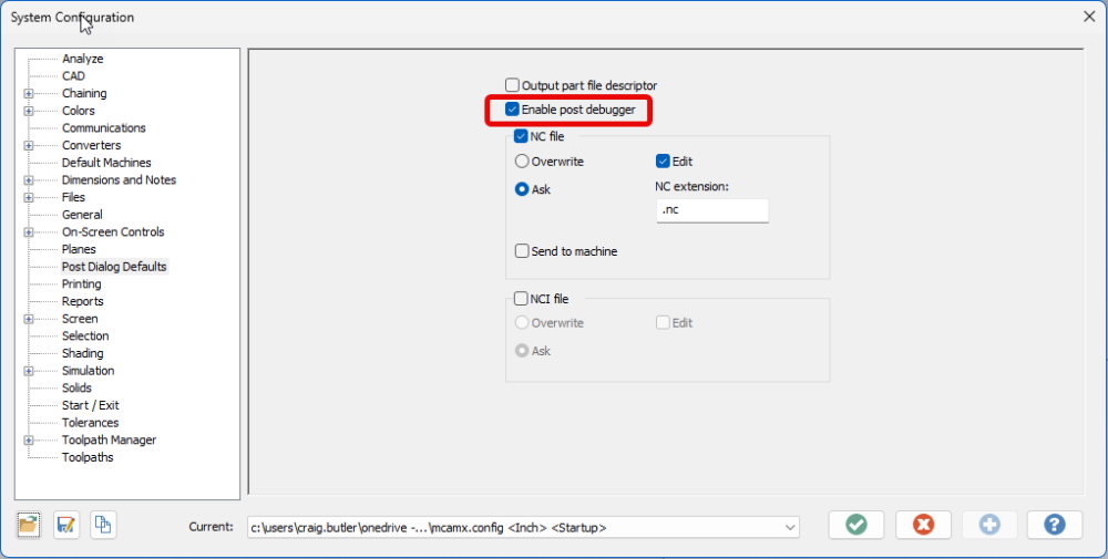

-
 Mahmoud Albakkar joined the community
 -
 I dont understand. Why are you asking here if you dont use mastercam?. What are you looking for?
 -
 I do not use mastercam.
 -
 If you are a legitimate user you can enter the site You have to register on a PC that has access to you Mastercam HASP or software license.
 -
 Ella Nickel joined the community
 -
I can not enter the site
-
 A Round Tuit joined the community
 -
 Madoda joined the community
 -
 rkornkven joined the community
 -
Not necessarily a tool change. Just trying to avoid adding another tool to the magazine, as its almost full and this machine has a bunch of jobs on it that run pretty much constantly. I ended up just adding a 1/8" ball mill though.
-
What Crazy was suggesting is to mill the "floor" of that feature with a small tool and then come in with an endmill that has the .062" corner rads and plunge in to finish the walls/corner rads. I assume you're trying to avoid doing that to save a tool change?
-
 LarryK131 joined the community
 -
We had 10 + seats of Powemill for the fidia's all with fidia controls... ( might be going to an aerospace shop with Doodan / Siemens) the automotive scene is toast
-
 JonathanGuanoRobayo joined the community
 -
 Teguiss joined the community
 -
Really for no other reason than the fact that I didn't want to add another tool just for that one feature. Also, the feature is inside of a pocket, so there are some limitations regarding reach. I edited the model, to just leave the feature I was asking a question about. However, as to your comment about using an essentially on size tool, that is creating a different issue, since I didn't anticipate the "cone" it's leaving on the .251" diameter floor. So I'll have to do something else. Garr has a 3.8" endmill with a .060" corner rad, so I think I'll just go that route. I had thought about that, but we don't get enough money for these parts to warrant a special tool. Garr having one on the shelf makes it make a whole lot more sense. Edit - Actually, scratch that. That's gonna have the same dish on the floor unless I have one made with a flat bottom. D'oh.
-
I have 2 Robofil 290 with automatic thread. Mastercam have 2 types of post for that machine. the first make a CMD file and several ISO files, and the second is a only ISO file. I use the second option. In the Tech Exchange page in Mastercam. com (HERE) you have those posts for free. But you will have to change some things to work well. You have to be registered of course:
-
 @clase de élite can help you
 -
here is the file if I did it correctly. PUN4358-003__PUNCH-03__D00_A2_NHC_Q01_24APR2024.x_t
-
So, it is often the case that the starting position for a TCP move can gouge or completely violate the part, if you're starting a path that is "on the far side of the part", or if you're transitioning between one side of the part, to the other. With a "Dynamic Work Offset or Tilted Work Plane" pre-position move, you're essentially 1) activating a work offset, 2) rotating the table into the correct starting position, 3) calling DWO/RTDFO to "dynamically align the active rotary face (A/C or B/C table position)" to a coordinate system attached to the part, 4) moving into a safe "XY Position", 5) using G43 to preposition Z with Tool Length Offset active, so you're driving the XYZ Tool Tip Position in coordinates which relate to the feature or zero position on the part. In terms of looking at the code, using G68.2 makes it really easy to gauge position and approach/retract moves, with a WYSIWYG (what-you-see-is-what-you-get) approach. With TCP on a Table/Table setup, Ben mentioned, "X6.7 is really the Z-Axis". The XYZ Coordinates for TCP are output as if the vectors are related to the "part setup at Rotary Zero", which means just "reading the XYZ values with G43.4 active" is not as straightforward as it would first appear. The anecdotal evidence I've seen shows that "DWO/TWP Pre-Positioning" generally solves this issue, which is why it is featured as an option in most advanced Post Processors. In the ideal setup, you pre-position using DWO/TWP, position tool tip using G43 (TLO), cancel TLO with G49, then cancel DWO/TWP (G69), and then invoke G43.4 Hxx, and if you output the same XYZ starting positions (or not), then when the TCP moves start, you're already perfectly in position because of the pre-position moves, and the path essentially "always works", or at least you can catch issues and diagnose root cause, much more easily by observation during the pre-position process. On a Table/Table VMC machine, using TWP, you're essentially always rotating a plane on an angled face into alignment with the XYZ machine axes. This means in general that "Z = Z" once G68.2 is invoked, provided it is setup properly (machine parameters) and called properly (NC Code).
- Last week
-
Well, I guess I'll chime in here a little bit. For the question of if you can activate G43.4 H## without a z on a Fanuc 31i, absolutely. Do it every day. Not sure on our parameter setup, but there is no movement, but the absolute coordinates jump. But we are on a head head machine. Shouldn't make much difference going to a table table design, actually it likely makes it a bit easier. 99% of the time, unless I am up against a barrier, our format is: G5.1 Q1 R# G54 G43.4 H G0 G90 X# Y#Z# B# C# S# M3 Basically speaking, I don't see any reason whatsoever if the machine doesn't move calling G43.4 H by itself in the current config. If the coordinates shift when you execute that line, and it doesn't move, it is configured not to. Then you can go about business as usual. Now on another note, and I am by no means an expert on Table/Table machines, but why would one preposition with G68.2 then cancel and run TCP instead? Seems confusing and cluttery. In the example above using G68/G53.1, the post has already calculated and moved to the desired table angles, why call it again? Is it just to make the machine and post are in agreement before you put a tool to the part? Anyway. Someday I hope to spend enough time on a table/table machines to understand some of these practices. I have spent ooodles of time tinkering with approach and retract code on the head/head configs, and head/head/table (with TCP on head but not table), and if I had motivation, have notes of thoughts on post structures and methods that would be HUGELY useful for readability and general simplicity of adjustment at the control if one were focusing on short run work. For the long run stuff it doesn't matter as much because you don't mind going back to CAM for quick edits, but when you are under the gun on a short run part, you just want to fix it in the program and move on. Then catch the CAM up later when you are back in the office. But someday I hope to have reason incorporate some really useful 5-axis features into a post. I'm rambling again....
-
Perfect, I'll take a look.
-
I've been a MasterCAM user for 6 years now, mostly using 2018-2019 version at my last shop. I downloaded the 2024 HLE and everything sems fine except there is an odd "waiting for printer connection" popup when I launch the program. It pops up for just a second and then disappears. Again, everything seems to function and work correctly, I just thought it was odd and I had never seen that before. Curious if that is normal?
-
The control is a Fanuc 31i-Model B5 and the machine is a 2019 model. I couldn't figure out how to message the parameters so I tried to attach them here instead. CNC-PARA.TXT
-
YOu may just end up having to set your Z to another place on the part... that's really weird though. Any chance you can output the parameters and DM them to me? What is the control and about how old is the machine ?
-
Just tried that and it didn't work either.
-
Have you tried G91 G43.4H? G90Z...
-
I am WEDM Department Manager. We have a Robofil 290 machine. Since my arrival I have written a subroutine for automatic rotation and referencing. Things are moving faster than I thought, but it's taking a really long time for the operator to draw a file on the screen. Even though I try this with codes like "DRS" in POST, the "DRS" code draws the drawings one by one on the graphic screen. This is not something we want. How can I make this machine do what I'm talking about? I wish you good forums. Thanks.. NOTE: I know that the "DRW" code is not valid for Robofil 290s. Machine: 1997 - Charmilles Robofil 290
-
Sometimes you have to do something weird with the work offset to get it to work.... but I'm thinking ther may be one or two other parameters... lemme check.
-
1301.7 is turned on. I tried turning it off but it didn't help. It is physically trying to move. I can see it move up .026 before it alarms. I'll have to keep this setting in mind if I'm ever getting other false overtravels. I'm going to look into this a bit more when I have some time. For now I'm going to set my Z0 off the bottom of the part instead of the top. Setting the Z0 lower solves the problem.
-

How to do a undercut program
Matthew Hajicek - Singularity replied to TERRYH's topic in Industrial Forum
I believe defining it as a T-slot cutter with corner radii will work.


.thumb.gif.b2f8d84f284177ecd2bf348424895690.gif)