


Leaderboard
.thumb.jpg.9ec558122c0479d844e9a9707b913308.jpg)


Popular Content
Showing content with the highest reputation on 11/11/2019 in all areas
-
But you can use a boundary that allows you to go outside the part and start. That is the secret of this toolpath. The stock is a part of the toolpath's power, but the labeling of some of the ability is lacking. Yes you want to start from the outside, but if you don't know the secret of using a boundary with a negative amount 2X to 3X your tool diameter then hard to know that even though the option greys out to start from outside it is starting from outside of the stock, but inside or center of the containment boundary. This is helped in many cause where I want to go into a tight areas, but still want the tool start from the outside. I then draw my boundary taking all of that into account and now I got a very nice toolpath. Next Step is stock models. Yes they grow the file exponentially, but when your looking to eliminate air cuts and get the most efficient toolpath then you take the time to use stock models; sometimes only need 3 to 5, but other times I might need 60 stock models in a programming file. Boundary is just a term and ignore the inside or outside in all reality if you are in open space by either using a large negative value or drawing a extremely large boundary. If you not in open space then play very close attention to how you want to use your boundary. Center or Inside are the ones I use the most. About 50/50 on using them. Inside or outside with a stock model in all reality is useless, but since they haven't made the software interface smart enough to not grey, but hide what you can't use then it create confusion. I have trained well over 50 programmers on this one topic and every time they see the process and ignore what the software is telling them they should be doing they get it and then are better for it. Had one customer fighting for weeks on a Ti part. In 5 minutes of showing him this he saved 3 hours of run time and was ready to not switch CAM Software's. He keep having to slow it down because it kept wanting to ramp into his part. He had the boundary for a reason, but just didn't grasp how important the room requirements were for the toolpath. Once we tweaked it to not hit the part next to it with .02 clearance and a bump out area for the tool to work into then he got perfect motion and not improved his tool life by 200%, but then reduce the 3 hours of run time. I figure that 5 minutes of time in one year saved them about $250k a year on the production job they were and are still running.3 points
-
I like Ron's suggestions a lot... he's the master... I always learn something from his posts. I agree it is almost always best to not get lazy... to create the extra surfaces needed to smooth out toolpath motion. But... if you're looking for a lazy way to throw just one toolpath at something complex, and still get a good result... IMHO, "pencil" is an overlooked toolpath. I like the way it sneaks up on pockets and internal corners. Just "uncheck" the "Maximum number of offsets" in "cut parameters." Check it out. Reko-Pencil-Finish2 points
-
I'm guessing that 118 ° is the default drill point setting in your customer's CAD system and they haven't put a second's more thought into it. The big aerospace firms have a spec for undefined drill points, smaller firms, not so much. This can be a real problem if you want to use 135° cobalt or 140° carbide drills Your safest best is to call and ask.2 points
-
Reverse selection button1 point
-
I always forget about boundaries, but I do use stock models. Luckily I don't make anything with a lot of operations at this job, as I do have experience with needing many stock models. Thank you Ron.1 point
-
If you hold down the scroll button on your mouse you can rotate. I use a 3D Connexion device though for rotating.1 point
-
1 point
-
Got it ,thank you Reko1 point
-
Try this one... Reko Pencil Finish1 point
-
I never have setup a threading tool in Mastercam the way Roger has set it up Sorry Roger. I always program Zero to the edge of the tool. I want my tool to go to .999 up against a 1.000 should then I can program .999 and know if the operator touches of the tool correctly it will never crash. By going off the center of the tool you run the risk of a crash. I do it like Peter is suggesting and never had a problem making a good thread yet.1 point
-
The beauty of the suggestion is the ability to do depth of cut and even a finish pass leaving .005 to finish. No other toolpath will work as slick and do the job he is needing IMHO. Have made many trim tools over the years and I use 3D contour for finishing complex shapes and all kind of things that when people see how I use it the way I use it they wonder how is it even possible. Geometry is a known and when you know the knowns then using it this way just becomes second nature.1 point
-
You already have the cutting edge defined which is the perfect tangential intersection of the side of the endmill. Grab that top intersecting edge and use 3D contour. Then in your incremental depth setting using -3mm and call it a day. You should be able to use Pencil and grab the 3mm radius and I think that should work. John's way is another way. May ways in Mastercam to do this on a 3 Axis machine.1 point
-
Here is that with a blend toolpath in the 2 transition areas. Blend Example to less complex solid Family comes first so keep the wife happy, but the better you get the more money you can make. I have worked and still work many hours for free learning my craft to make me better. I am still learning and still improving and each day I am always trying to do better than I did the day before.1 point
-
I threw this together to give you a different way to approach it. I wish I had the solid model it would have been faster to fill in the areas, but I broke out my old surface creation methods and even used the Verisurf Power Surface to fill into two of the areas. Yes this will go over the pockets, but I would be okay with that as it gave me motion I would like to see on a machine. I can think of many other ways to approach this shape, but want to see if this is what your looking for or not. 5th Axis Equal Scallop Concept1 point
-
I guess that is where my crazyness kicks in. I would not finish that with one toolpath. I would finish that with several different toolpaths. Finishing that with one toolpath is lazy and will not produce the results I would be willing to accept or consider acceptable.1 point
-
Hello Jeremy, This is a known issue and is being resolved currently. The work around is to turn off the "Max Distance" field in the post settings of the SImulator Options page. As you have found it does get reset. It is due to the infinite possibility of moves to get from on position to the other. Ken Fortier Product Owner, Integration CNC Software, Inc.
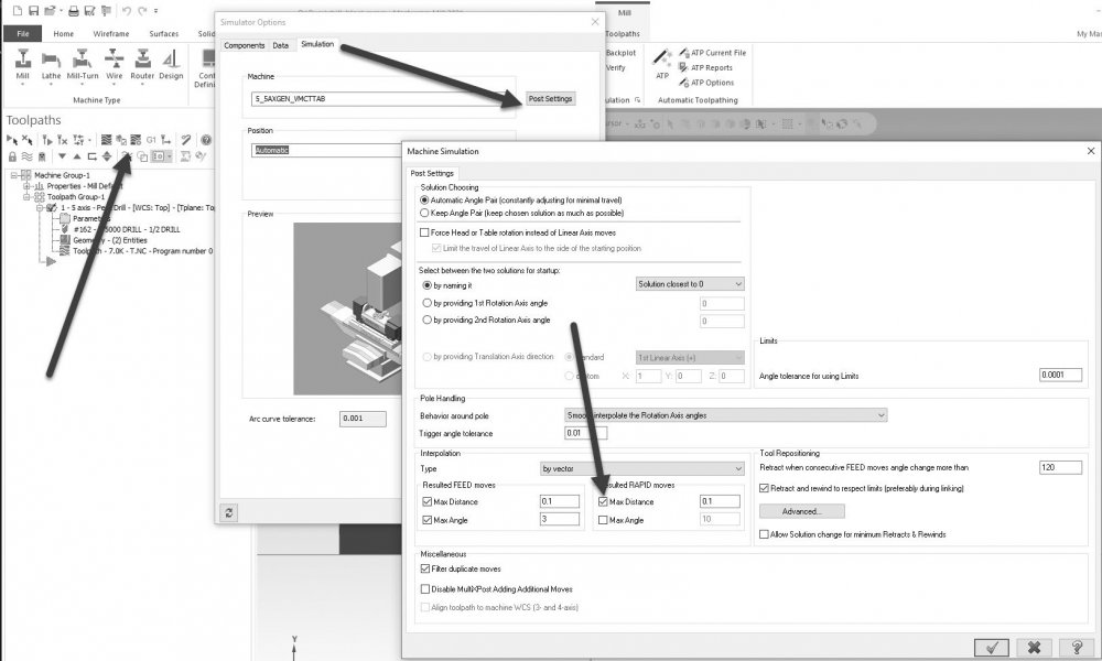 1 point


