Slepydremr
-
Posts
294 -
Joined
-
Last visited
-
Days Won
1
Content Type
Profiles
Forums
Downloads
Store
eMastercam Wiki
Blogs
Gallery
Events
Everything posted by Slepydremr
-
How do you set up your tools (speeds/chip load) while programming?
Slepydremr replied to neurosis's topic in Industrial Forum
I use MCam to figure the feeds and speeds. I have a generic material definition that has "Base cutting speed (SFM)" set to 100, and "Base feed per tooth" set to 100. Then on the individual tools I simply ignore that it says "% of matl cutting speed" and type in the actual sfm, same for the "% of matl feed per tooth", i type in the actual chip per tooth i want. Now the Calc Feed and speed works fine. -
well Matt here's what I've come up with so far It's looks a bit messy, but so far it works with contouring and pockets when there is a sharp corner I haven't tested it with anything too complicated yet so please be cautious mr3 is the feed multiplier mr4 is the minimum radius before it starts to slow down in corners mr5 is the minimum angle before it considers it sharp mr6 is the distance before the sharp corner to start slowing down. the trial i was running was mr3 .5 mr4 .05 mr5 140 mr6 .02 And it seemed to be working okay you need to add the varables len_a : 0 #Formatted absolute value for a length calculations len_b : 0 #Formatted absolute value for b length calculations len_c : 0 #Formatted absolute value for c length calculations len_ang : 0 #Formatted absolute value for angle calculations nex_rad : 0 #Formatted absolute value for c incremental calculations and add these formatted variables fmt "X" 2 brk_x #X position output fmt "Y" 2 brk_y #Y position output and then put this in your plinout section plinout #Output to NC of linear movement - feed mr3$ = abs(mr3$) mr4$ = abs(mr4$) mr5$ = abs(mr5$) mr6$ = abs(mr6$) if absinc$=0 & zabs = prv_zabs & mr6$ >0, [ len_a = sqrt((xabs-prv_xabs)^2 + (yabs-prv_yabs)^2) if nextop$ = 1, [ len_b = sqrt((nextx$-xabs)^2 + (nexty$-yabs)^2) len_c = sqrt((nextx$-prv_xabs)^2 + (nexty$-prv_yabs)^2) if len_a <> 0 & len_b <> 0, [ len_ang = acos((len_a^2+len_b^2-len_c^2)/(2*len_a*len_) ] else, [ len_ang=180 ] if len_ang < mr5$, [ if len_a < mr6$, [ feed = feed*mr3$ ] else, [ brk_x = xabs-((xabs-prv_xabs)*mr6$/len_a) brk_y = yabs-((yabs-prv_yabs)*mr6$/len_a) pcan1, pbld, n$, sgplane, `sgcode, sgabsinc, pccdia, [if brk_x <> xabs,brk_x], [if brk_y<>yabs,brk_y], pzout, feed, strcantext, pcoolant, e$ feed = feed*mr3$ ] ] ] if nextop$ =2 | nextop$ = 3, [ nex_rad = sqrt((nextx$-nextxc$)^2+(nexty$-nextyc$)^2) if nex_rad < mr4$, [ brk_x = xabs-((xabs-prv_xabs)*mr6$/len_a) brk_y = yabs-((yabs-prv_yabs)*mr6$/len_a) pcan1, pbld, n$, sgplane, `sgcode, sgabsinc, pccdia, [if brk_x <> xabs,brk_x], [if brk_y<>yabs,brk_y], pzout, feed, strcantext, pcoolant, e$ feed = feed*mr3$ ] ] pcan1, pbld, n$, sgplane, `sgcode, sgabsinc, pccdia, pxout, pyout, pzout, feed, strcantext, pcoolant, e$ ] else, [ pcan1, pbld, n$, sgplane, `sgcode, sgabsinc, pccdia, pxout, pyout, pzout, feed, strcantext, pcoolant, e$ ] here's the test code without the sharp corner check N108 G43 H1 Z1. N110 Z.25 N112 G1 Z0. F50. N114 Y-.9 F100. N116 G3 X0. Y-1. I.1 J0. N118 G1 X.99 N120 G3 X1. Y-.99 I0. J.01 N122 G1 Y0. N124 Y.99 N126 G3 X.99 Y1. I-.01 J0. N128 G1 X-.99 N130 G3 X-1. Y.99 I0. J-.01 N132 G1 Y-.99 N134 G3 X-.99 Y-1. I.01 J0. N136 G1 X0. N138 G3 X.1 Y-.9 I0. J.1 N140 G1 Y-.8 N142 Z.2 N144 G0 Z1. N146 X-.1 N148 Z.25 N150 G1 Z0. F50. N152 Y-.9 F100. N154 G3 X0. Y-1. I.1 J0. N156 G1 X1. N158 Y0. N160 Y1. N162 X-1. N164 Y-1. N166 X0. N168 G3 X.1 Y-.9 I0. J.1 N170 G1 Y-.8 N172 Z.2 N174 G0 Z1. here's code with the misc values set N100 G20 N102 G0 G17 G40 G49 G80 G90 N104 T1 M6 N106 G0 G90 G54 X-.1 Y-.8 S10000 M3 N108 G43 H1 Z1. N110 Z.25 N112 G1 Z0. F50. N114 Y-.9 F100. N116 G3 X0. Y-1. I.1 J0. N118 G1 X.97 N120 X.99 F50. N122 G3 X1. Y-.99 I0. J.01 N124 G1 Y0. F100. N126 Y.97 N128 Y.99 F50. N130 G3 X.99 Y1. I-.01 J0. N132 G1 X-.97 F100. N134 X-.99 F50. N136 G3 X-1. Y.99 I0. J-.01 N138 G1 Y-.97 F100. N140 Y-.99 F50. N142 G3 X-.99 Y-1. I.01 J0. N144 G1 X0. F100. N146 G3 X.1 Y-.9 I0. J.1 N148 G1 Y-.8 N150 Z.2 N152 G0 Z1. N154 X-.1 N156 Z.25 N158 G1 Z0. F50. N160 Y-.9 F100. N162 G3 X0. Y-1. I.1 J0. N164 G1 X.98 N166 X1. F50. N168 Y0. F100. N170 Y.98 N172 Y1. F50. N174 X-.98 F100. N176 X-1. F50. N178 Y-.98 F100. N180 Y-1. F50. N182 X0. F100. N184 G3 X.1 Y-.9 I0. J.1 N186 G1 Y-.8 N188 Z.2 N190 G0 Z1. Notice i actually made it break the lines .020" before a small arc so it slowed down before it hit the radius. I hope this works for you, or at least gets you going in the right direction.
-
In your parc section you should be able to add the following line if abs(arcrad$) < mr4$, feed = feed*mr3$ here is a the whole parc section from the Generic Fanuc 3X Mill post i have. Notice the line i added at the end just before the end. parc #Select the arc output if (plane$ = zero & (arctype$ = one | arctype$ = four)) | #XY Plane (plane$ = one & (arctypeyz$ = one | arctypeyz$ = four)) | #YZ Plane (plane$ = two & (arctypexz$ = one | arctypexz$ = four)), #XZ Plane [ result = newfs(two, iout) result = newfs(two, jout) result = newfs(two, kout) ] else, [ result = newfs(three, iout) result = newfs(three, jout) result = newfs(three, kout) ] if (plane$ = 0 & arctype$ < five) | (plane$ = 1 & arctypeyz$ < five) | (plane$ = 2 & arctypexz$ < five) | full_arc_flg$ | arc_pitch$, [ #Arc output for IJK # If you do NOT want to force out the I,J,K values, # remove the "*" asterisks on the *i, *j, *k 's below... if plane$ = zero, *iout, *jout, kout #XY plane code - G17 if plane$ = one, iout, *jout, *kout #YZ plane code - G19 if plane$ = two, *iout, jout, *kout #XZ plane code - G18 !i$, !j$, !k$ ] else, [ #Arc output for R if abs(sweep$)<=180 | (plane$ = 0 & arctype$ = five) | (plane$ = 1 & arctypeyz$ = five) | (plane$ = 2 & arctypexz$ = five), result = nwadrs(srad, arcrad$) else, result = nwadrs(srminus, arcrad$) *arcrad$ if abs(arcrad$) < mr4$, feed = feed*mr3$ ] HTH
-
Mike, I'm glad it's working for you at 1st glance I thought it might kick out feed changes when it shouldn't. I'll have to test it out more when i get a chance. Matt, Sharp corners pose a bit a problem, at least for me, the math to calculate the angles gets a little tricky, but can be done. But then once you know it's a sharp corner you need to find your spots to adjust the feed rate. So adding in a breaking point to just before your sharp corner to slow down might be a bit of a trick. I'll certainly give it a shot when i have some free time at home tonight.
-
I think there are times when you have a large radius with only a small move in i or J so doing them separately you might end up slowing down a larger radius than you meant too, to prevent this you could simplify the math to calculate the radius. [ if iout, [if iout <mr4$ & iout >-mr4$ ,feed = feed*mr3$] else, if jout, [if jout <mr4$ & jout >-mr4$ ,feed = feed*mr3$] ], becomes [ if i$ <> 0 | j$ <>0, [if sqrt(i$^2 + j$^2) <mr4$ ,feed = feed*mr3$] ], HTH edit: for example your post would slow down the following .750" radius even if you had the tolerance set to .100" N16 X1.75 Y1.9987 N18 G3 X.9987 Y2.75 I-.75 J.0013 N20 G1 X-.0013 Y2.7483 By checking the actual radius it will prevent that from happening.
-
When you bring in your second part save the file as that part name then move your first part. all its tool paths and WCS to the new parts position with Xform 3-D . Modify your tool paths to the new part then delete the originally programmed part and no one will ever know it was there. We program leaving our parts in aircraft coordinates and do this all the time with no issues.
-
I think it could be done in the post using the nc file name as a variable to define the directory. I don't have the time to test my theory right now, but maybe that will help get you set in the right direction.
-
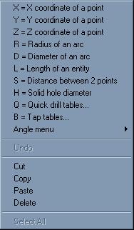
Having the big select dialog box show up in those comment windows would be handy. I'm referring to this box. Is that what you're asking as well?

-
We've run in to this problem occasionally. I'm sure the post could be setup to make it easier, but I don't believe you can do it with a canned cycle. The few times I've had to do it I just used point to point tool path like you mentioned.
-
Similar situation here. We use WCS for all parts, including 5-axis. One of our customers does revisions so often that needing to move the part to the main origin and getting it perfectly aligned every time just to do a quick compare to see what pilot holes they shifted would be a bit of a headache. This customer also creates parts that have very few if any straight edges that one would use to align from.
-
My controller file disappers whats up?
Slepydremr replied to RObert TImby's topic in Industrial Forum
So we've finally updated to X6 MU2 today, and this is of course the first issue I ran into. Since all of our files our shared on the network it is pretty necessary to get these working right so I've found a small, quicker I think, work around. 1. Make all the changes you want to your control file. 2. Click Save As (DO NOT HIT SAVE!!!) 3. When the prompt box appears letting you know data was changed click YES. 4. When the Save As window appears Rename the file to junk or trash or anything you desire, just not what the original name was. 5. Click check mark to go back to Machine Definition Manager window. 6. Notice that the control file is listed as your junk or trash file, click the folder and reselect the actual file you want to use. 7. Save and then exit. Tada all done! This has to be done every time you make a change to your control file, but it does save you from searching for your temp file, and you know exactly where and what control file you're using. Hopefully this makes sense and I'm not so late to the updating party that there are still people that may find this helpful. -
Try saving the file you are trying to merge as a .step or .x_t file. Then merge that file into your other .mcx-5 file. This has worked for me several times.
-
Point toolpath. Manual entry (as code)"M00 (LOCATE PART)" Point toolpath for retract.
-
which thread mill to use,single point or multi
Slepydremr replied to PaceToolmaker's topic in Industrial Forum
I prefer multi-tooth tools over single-point, as long as you can get the reach you require. The only downside is requiring different tools for different pitches. Where a single point tool could do multiple threads but will require more passes. -
So I'm doing a simple transform by coordinate in X5 and I notice that not all the of depths in my pocketing routines are being translated. Bottom left is the original part. upper three are all translated tool paths from that transform operation. anyone else experiencing this. Also I changed the source to geometry and now all my depth cuts are there. So I have solved my problem but I would still like to find out what's causing this.
-
You may need to check your parameters. If the post thinks you're posting for a horizontal then it wants Front to be A0 so by having your T/C planes set to top it's putting out a rotation to get there. Easy check would be to set WCS to Top and T/C planes to Front and try that out. If that fixes it then you need to find that parameter and switch it for vertical.
-
It looks as though you have. Try doing a simple 2d contour with no ramp. Also when using leadin-lead out and wear cutter comp. you must have a lead in line with any arc you're using. It can be a pretty short line but you're first move must always be linear.
-
Out of curiosity..What type of operation are you starting that first tool with? I'm just wonder cause it is feeding in all 3 axis like the beginning of a pocket or something and if it is a pocket the G comp will not get turned on till the last pass. also did you do a search of all G-code to see if a G41 is turning on later? The toolpath parameters should be what always controls the Comp
-
Happens all the time. Easiest way to remove that entity is to have only that level on then do a screen unblank all entities, hit enter, then hit delete, then enter. Just make sure you only have the level or levels on that show the strange 1 entity.
-
In before lock.
-
Stuart, In your program are you originally starting from front view (which would be B zero) and rotating around what would be Mastercams Z axis but the machines Y axis? So that right side view would be B90 and left side view B-90? Also when you are making toolpaths on different rotations make sure you're not changing the WCS to that new view only the T-plane/C-planes should be changing.
-
depending on which format you want from this section code: # -------------------------------------------------------------------------- # Format statements - n=nonmodal, l=leading, t=trailing, i=inc, d=delta # -------------------------------------------------------------------------- #Default english/metric position format statements fs2 1 0.7 0.6 #Decimal, absolute, 7 place, default for initialize ( fs2 2 0.4 0.3 #Decimal, absolute, 4/3 place fs2 3 0.4 0.3d #Decimal, delta, 4/3 place #Common format statements fs2 4 1 0 1 0 #Integer, not leading fs2 5 2 0 2 0l #Integer, force two leading fs2 6 3 0 3 0l #Integer, force three leading fs2 7 4 0 4 0l #Integer, force four leading fs2 9 0.1 0.1 #Decimal, absolute, 1 place fs2 10 0.2 0.2 #Decimal, absolute, 2 place fs2 11 0.3 0.3 #Decimal, absolute, 3 place fs2 12 0.4 0.4 #Decimal, absolute, 4 place fs2 13 0.5 0.5 #Decimal, absolute, 5 place fs2 14 0.3 0.3d #Decimal, delta, 3 place fs2 15 0.2 0.1 #Decimal, absolute, 2/1 place fs2 16 1 0 1 0n #Integer, forced output you'll need to change the number here code: fmt F 15 feed #Feedrate example I'd have to change mine to code: fmt F 2 feed #Feedrate
-
Using an STL for stock won't display on verify
Slepydremr replied to VINK's topic in Industrial Forum
Make sure the WCS you're saving the stl in is also the WCS you're using for Stock Setup. I always set mine to TOP, and when I'm saving my STL's make sure that WCS is set to top. -
Make small changes, save then test. Don't try to modify too much at once that way if something doesn't go right it's easier to find the problem.
-
Depends on the drill chart you're using to get the F&S I've seen some that are IPT and some that are IPR. My Garr drill chart is IPT, but thats carbide. It should be noted somewhere on the chart what the manufacturer is going by. If not I'd play it safe and go IPR. edit: It took me a bit to find the chart but my Standard HSS chart is IPR. Hope that helps.