Grievous
-
Posts
166 -
Joined
-
Last visited
-
Days Won
1
Content Type
Profiles
Forums
Downloads
Store
eMastercam Wiki
Blogs
Gallery
Events
Everything posted by Grievous
-
All of you... watch and learn https://twitter.com/engineers_feed/status/1103628364684972032?lang=en
-
So...do you need to do some 4x simultaneous or just index positioning?
-
My question stands..Why do you need to check the tool against the workpiece?
-
Question: Do you need to check for collision of tool against the workpiece ? Why? .......simulation tolerances??
-
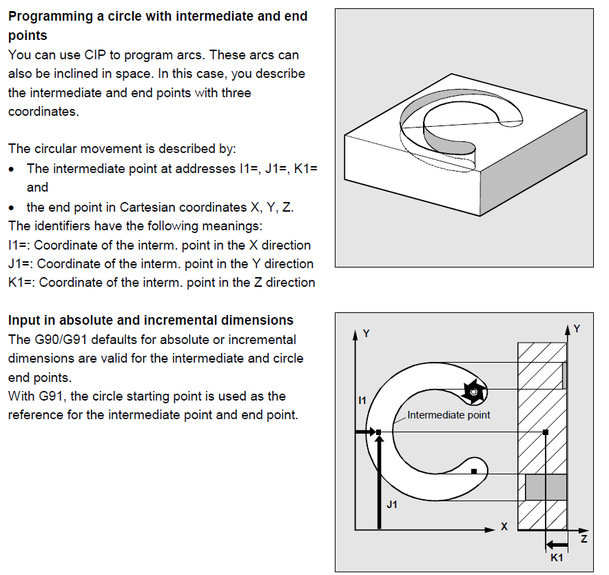
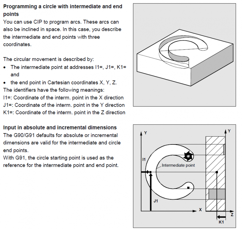
You will be able to do that kind of movement on a controller like Sinumerik, but mastercam won't be able to handle that type of movement. If you close that arc you will see that it is inclined in space.
-
SLOT-NEWest-new.mcam
-
Yes that is what I'm doing..I replaces in post the tool tip comp command with a call to a cycle in which I can set the limits I want...for example on a matsuura5X where A axis goes +11.5 to -111.5 I do this way: TRANS_5A(0,-110.) ;TOOL TIP COMPENSATION ON ;************************************ REPEATB DATUM ;SET ACTIVE WPC N3 G90 G0 X4.362 Y-6.9919 Z10. A3=0. B3=-.9918 C3=-.1277 ...etc The cycle looks this way.. PROC TRANS_5A(REAL UPPER_LIM, REAL LOWER_LIM) SBLOF DISPLOF ;usage TRANS_5A(0,-90) IF (UPPER_LIM > $TC_CARR32[1]) GOTOF ALLARM1 IF (LOWER_LIM < $TC_CARR30[1]) GOTOF ALLARM2 IF (UPPER_LIM==0)AND(LOWER_LIM==0) ELSE $MA_POS_LIMIT_PLUS[AX5]=UPPER_LIM ; $MA_POS_LIMIT_MINUS[AX5]=LOWER_LIM ; ENDIF $MC_TRAFO5_ROT_AX_OFFSET_1[0]=$P_UIFR[$P_UIFRNUM,A,TR] $MC_TRAFO5_ROT_AX_OFFSET_1[1]=$P_UIFR[$P_UIFRNUM,C,TR] NEWCONF ; STOPRE ; TRAORI M132 M17 ALLARM1: MSG("UPPER LIMIT IS > "<<$TC_CARR32[1]<<" /REPROGRAM THE COMMAND") M00 M30 ALLARM1: MSG("LOWER_LIM IS < "<<$TC_CARR30[1]<<" /REPROGRAM THE COMMAND") M00 M30
-
Just an idea...When I have a machine where one axis goes ..let's say -5 to +180, to avoid the issue, I rewrite the axis limit from 0 to 180. After I finish I write back the limits. I use vectors for 5x programing , not direct machine axis.
-

Has anybody else set up a 5 ax post for the new DMU-60 EVO
Grievous replied to pullo's topic in Industrial Forum
Just a thought....you can set your post, to give you in M128 mode(5x) the surface-normal vectors NX, NY, NZ, instead of your machine axes. Same code will work in a machine with a different kinematic also. -
For 100% accurate locating, someone can use this https://www.emastercam.com/forums/topic/92601-how-to-locate-your-part-in-machine-simulation/?tab=comments#comment-1142547 SimTransform.xlsx
-
Parallel Surface toolpath
Grievous replied to Jordi Rosas's topic in Post Processor Development Forum
When using parallel surface tool path, the resulting motion is similar with a Brownian motion....lol
-
If you want to have the values of your wo in your program, you can write them in like this(similar to $P_UIFR[1]=CTRANS(X,0,Y,0,Z,0)in sinumerik or G10 in Fanuc) 1 FN 17: SYSWRITE ID 503 NR37 IDX1=-10. 2 FN 17: SYSWRITE ID 503 NR37 IDX2=-20. 3 FN 17: SYSWRITE ID 503 NR37 IDX3=-30. 4 FN 17: SYSWRITE ID 503 NR37 IDX4=+0. 5 FN 17: SYSWRITE ID 503 NR37 IDX5=+0. 6 FN 17: SYSWRITE ID 503 NR37 IDX6=+123. ...where NR37= your datum number in this case 37...you can use also(NRQ339 to match your CYCLE DEF 247 number) IDX= axis........IDX1=X axis...IDX2=Y axis...IDX3=Z axis....IDX4=A axis.....IDX5=B axis....IDX6=C axis To read a value from an datum use: 1 FN18: SYSREAD Q4 = ID503 NRQ339 IDX6 in this case u copy the value of C axis from datum number Q339 into Q4 parameter. Hope it helps
-
pullo ... It does not, but there are other ways to achieve that with Fanuc
-
DMG Ultrasonic 20 linear 5Axis machine
Grievous replied to MSL's topic in Post Processor Development Forum
I 100% disagree with you, based on my experience with this machine. This is a 5x Sinumerik machine. Nothing fancy. There are no special/manufacturer codes to make this machine run, except the enabling ultrasonic mode, which is highlighted in the book of machine, everything else are standard sinumerik cycles and codes like you said,Traori, Cycle800, Cycle832..etc. The post builders don't need DMG to hold their hands when they do a post for a controller, more like just to know the special manufacturer cycles and codes and integrate them, and like I said , they are highlighted in the machine book, which for sure he got(at least I got it). And when you have issues understanding them, then that's when you ask builder. I don't see the reason to call DMG to explain you how Cycle800 or Traori works. I did my post myself based on an existing post I had. Actually all Sinumerik machines here(3x 4x and 5x) have 1 single post with switches. -
DMG Ultrasonic 20 linear 5Axis machine
Grievous replied to MSL's topic in Post Processor Development Forum
If the post is not outputting the correct codes, then it is not DMG fault....just my opinion. DMG is selling you a machine with a controller on it. Except some manufacturer cycles made by DMG(for which you got a book I assume), everything is a Sinumerik control. -
DMG Ultrasonic 20 linear 5Axis machine
Grievous replied to MSL's topic in Post Processor Development Forum
I will not post codes for you...sorry..against my work place policy. But I can 2nd CMillman here. You will need a 5x Sinumerik post with some specific customization for this machine, especially for how to enable the ultrasonic mode...(thru misc val ). That's it...The codes I share are hand customized .something I like to do sometime, since there is no CAM system who can give me the type of format I want sometime. So keep it simple in the beginning. Get a good 5x Sinumerik post, then work with DMG and your post builder to incorporate the ultrasonic part in it. Good luck. -
DMG Ultrasonic 20 linear 5Axis machine
Grievous replied to MSL's topic in Post Processor Development Forum
We have one here. See attached codes. I don't know about other ppl experience, but here DMG support has been great. Very knowledgeable ppl. ultra20.zip -
The cycle is just a combination of multiple commands/codes. If you read the explanations you will find that you can program functions separately, like FFWON SOFT G642. Give them a try.
-
CYCLE832 Some explanations/examples in here(starts from page 63) https://cache.industry.siemens.com/dl/files/454/37335454/att_110322/v1/SIN_WF5_0509_en.pdf
-
Ethernet service software replacement for cimco nfs?
Grievous replied to Smit's topic in Industrial Forum
We use for all Heidenhain TNCremo (it's free) software https://www.heidenhain.de/de_EN/software/ -
I remember that long time ago we used on one machine something like below, 'til we change the param G91G49G53G0Z0
-
Gotta go home..cannot finish it...but that's how I would do it... ...I split it in 2 for safety...to avoid pole singularities issues .. (dunno what machine kine this guy has) ...btw in case u dont have a 15mm cutter...lol SEAL_GROOVE.mcam
-
Compensation Poll - Take the poll
Grievous replied to Matthew Hajicek - Singularity's topic in Industrial Forum
Well...nobody was telling you how program your machines. You just quoted a statement about a threadmilling, and you implied that you can lead in in 0.002 and that's why you are using wear: " Right here is exactly why I use wear. ...etc etc" .and implying u cannot do it same thing with control. You can..btw.. -
Compensation Poll - Take the poll
Grievous replied to Matthew Hajicek - Singularity's topic in Industrial Forum
You can do that with control also ...no problem...so?...anyway I dont think u wanna do a threadmilling just with 0.002 room to lead in? -
I don't get what this pool will achieve...but anyway. What I can tell you is that, all of you who just used Mastercam to program with control comp you are bias. I programed in another software for years and I didn't have ever any issue using control comp. In other parts of the world (especially Europe, I don't know about Asia or Africa or Australia) it is opposite...ppl they are inclined to use control comp. Mastercam sucks at how its handling control comp. That was the 1st thing I noticed when I start using it 12y ago. There is a reason that in any controller the offset registry call for tool length, and for TOOL RADIUS(some of them tool Ø depending on settings) to be inputted in the controller so specific functions can be performed...like working with compensation....on tool direction(aka g43) and on tool diameter(aka g41 g42). There is a culture who evolved over the years (more in North America) from the inability of a software (who is the best seller in a specific market), to handle some machine functions. One example...I know that most of you guys know, (when we are talking about how ppl are using tool length compensation), that are still ppl who r working different, by using G52 option..and that what is happening when ppl are using wear comp...they achieve their goal by doing things different..they don't put tool rad in machine ..controller compensate that...or with ppl who r using customized posts where they do 5x by puting their tool length in the program. ...all theese methods are TOTALLY fine, 'cuz you achieving your goal to machine parts.....but by making statements that one way is better then another, without having more experience with another software or controllers it is bias. Mastercam is just a tool, who should be used to simplify the process of creating codes for a machine equipped with a specific controller. For a controller like Sinumerik, Mastercam it is just scratching the surface...you can access not even 50% from what that controller can do....I'm saying all these to point that you should not judge based by what tool you are using......anyway... YES...if you are using Mastercam, then you are better by using wear vs control, but not because this is the right way but because that's what your tool(Mastercam) can do better when working with compensation.