NOTW Programmer
-
Posts
469 -
Joined
-
Last visited
Content Type
Profiles
Forums
Downloads
Store
eMastercam Wiki
Blogs
Gallery
Events
Everything posted by NOTW Programmer
-
Trim curves to plane or surface in X6
NOTW Programmer replied to Bill Cronkhite's topic in Industrial Forum
That That should be under the Create->Curve->Trim->Trim To Curves menu. -
Last I checked( 10 minutes ago), when I change the pitch and crate a new tool, my version of MCAM updates the feedrate to match the RPM x PITCH.
-
Where is that manager, I cannot find it in the CAD settings branch.
-
Whats the scale again, 1/10th ?
-
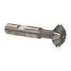
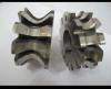
So what if you have different sizes of the same tool, like a concave, convex, or double angle cutter. Do I have to redraw for each thickness or will MCAM scale like it does for all other tools.

-
The tiles are cumbersome, they should have a General tile representing the App, and a drop down button to expand into what ever else there is in the StartMenu folder. Tested it in during Beta and X5 worked OK.
-
They must not account for backlash then, last I remember unless you have it hooked up to a Haas machine there is nothing you can do. All that is available is the M code for it to index to the predefined angles set on the rotary control itself. Which indexer do you have, and what do you need it for on a Horizontal ?
-
Trouble Logging On To eMastercam????
NOTW Programmer replied to John Hill @ Poplar Hill Machine's topic in Industrial Forum
Same here I find that OD, but perhaps it wants to read that we have the latest IE9. -
So is it starting at the top and going down ? or ab the Bottom and going up, which I would prefer if I was surfacing a countersink on a hole.
-
Another Transform Offset Posting Probrem
NOTW Programmer replied to Scrump's topic in Industrial Forum
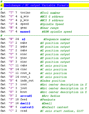
Check this in your post, pwcs #Work Offset setting if wcs_mode = two, # 'E' fixture offset mode [ sav_frc_wcs = force_wcs if sub_level$ > 0, force_wcs = zero if workofs$ <> prv_workofs$ | (force_wcs & toolchng), [ g_wcs = workofs$ + 1<----this is what makes the Work Offset increase if it is different from one toolpath to the next, or in your case using the Xform Toolpath. *g_wcs ] force_wcs = sav_frc_wcs !workofs$ ] -
What about the Solid, a pic would help !
-
CHECKING MINOR DIAMETER ON EXTERNAL THREAD
NOTW Programmer replied to Larry1958's topic in Industrial Forum
Have a tool manufacturer make you a tool, sumitomo can do that for sure. -
Go to their factory and have them run a test on some of your parts, they have offered me to come over but my partner says the same, not strong or heavy enough. They have linear guides like haas, and the weight is a joke.
-
In the Toolpath Parameters under the Cut Parameters branch there is a Tip Comp option, you have that set to center being a bullnose endmill it drops down the radius amount. Change it to Tip.
-
Programming in space, create a Solid Layout.
NOTW Programmer replied to NOTW Programmer's topic in Industrial Forum
Does it project to the current Z level ? I have never used it. -
Programming in space, create a Solid Layout.
NOTW Programmer replied to NOTW Programmer's topic in Industrial Forum
Yes, boundaries, center points, you name it; its just easier with the layout tool. Not everything works as we would like though. What do you do when you need these types of wireframe Jay ? -
Programming in space, create a Solid Layout.
NOTW Programmer replied to NOTW Programmer's topic in Industrial Forum
Im talking about where the view is created not which view it creates. How would you do what I want, I was taught never to chain on the solid as if it goes corrupt I will lose all toolpath associativity. -
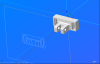
HI, I am programming a part in 3D space and would like to create a wireframe view with the Layout utilty. The utility is creating the view on what used to be the top view, instead of what is now the new WCS.
-
You need to enable the debugger to find the variable triggering this, what post do you have or upload so I can modify for you.
-
How about this:
-
Last I checked there is a documented procedure for this. See attached !

-
Fadal / Post help, O0000 to output O0001 ?
NOTW Programmer replied to Fred @ Slate Industries's topic in Industrial Forum
You could alternatively use these two places to stablish the program# as 1, use the first when setup your machine group properties before any toolpath has been created; use the second when there is already toolpaths or you simply forgot to do it before hand.

-
Typically you would create a Main X6 Folder with all your libraries; tools, holders, ops, CNC machines, Controls, Posts, etc. Similar to what we have in the shared Mcamx6 Folder on the PCs. Attached is an image of what I have, I could go further and Group all the Mill Folders in a Main MIll Folder. but thats something Im still trying to fit into schedule.

-
I thought it was Toolpath Xform->Rotate, Choose the Top plane as your Rotation view, but I get some funky looking backplot. I resorted to using two Xforms but the backplot still mills for the inside of the cube on the opposite side to the Source OP. To output subs all you have to do is click on Subprograms towards the right, in the Types and Methods tab of the Xform Toolpath feature.


-
Guess that was that, did anything happen about this endeavour !