Chally72
-
Posts
499 -
Joined
-
Last visited
-
Days Won
32
Content Type
Profiles
Forums
Downloads
Store
eMastercam Wiki
Blogs
Gallery
Events
Everything posted by Chally72
-
This is a known problem in 2020 where we're feeding back in from the retract for each peck, so deep holes or holes with shallow pecks have backplot cycle times that are farther and farther off. 2021 addresses this to correctly account for the rapid down to clearance in the cycle time. A workaround in 2020 right now would be to swap to a chip break cycle in that operation temporarily to backplot it and see a more accurate cycle time if your boss needs a ballpark time.
-
You can actually string together multiple points in the Point toolpath, but for ease of readability and edits if ever coming back to the file, I split it out into individual toolpath segments.
-
Attached is a file with an Iscar 0.630 self centering drill being driven by a point to point toolpath (Operations 13-16) to drill holes with no spotting in the angled faces of this part. We needed to come in with a slow feed until we hit full diameter engagement, then change the feedrate to drill the rest of the hole. The green wireframe you see there is what I drew to provide the necessary Z points for each change in feed or other parameters that I wanted to make. Here's a link to a video of the part being cut- skip to 1:20 for the angled face drilling: https://www.youtube.com/watch?v=KlV-tqUrlIM Let me know if you have any questions! DEMO PART 1018.mcam
-
For 2020 and before, I would do this with driving the drill around with Point toolpath to make RPM/speed changes mid-hole where I wanted to. For 2021, there's a new Advanced Drill toolpath that allows you to build your own custom drill cycle, segment by segment, and individually control coolant settings, RPM, feed, peck settings, and manual entry and comment insertion for each segment. Post output is not canned cycle, but easily readable G1/G0 movement that in our testing works very well with existing posts. I know I've responded with 2021 plugs on the last three posts now, but there's an avalanche of new toys that I've been using nonstop here in Applications.
-
Are you sure Mastercam is utilizing the dedicated graphics card? Have you forced it to do so in the Nvidia manager? What are the average sizes of these files? Of the toolpaths? A single high end graphics card is always going to be a lot better than two SLI-bridged lower end cards. Even for gaming purposes at home where I have all the time in the world to troubleshoot driver issues and play with hardware, I would never go with a dual GPU solution.
-
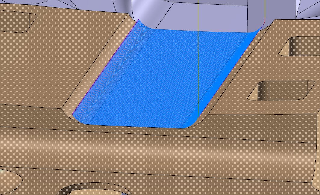
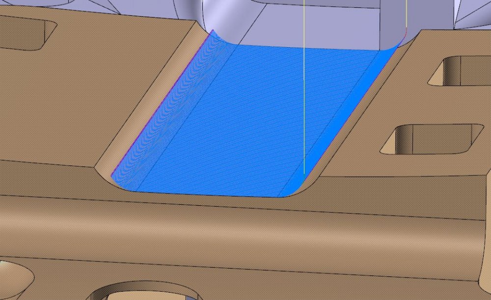
Here's an example of the differences in choice between Tool Tip and Tool Contact Point. Say I want to cut the valley area, including the filleted valley walls, in this part with a raster. I'll set up a raster against those 3 surfaces, and set my containment boundary to use Silhouette boundary, which produces the same thing as if I created a wireframe chain containment area around those 3 surfaces. Using Tool Tip contain, this is what we get: Note how we drive the tool tip all the way to the containment boundary edge. On this geometry, we're transitioning across a sharp edge at each end, and most of that motion is wasted time, because we already cut as much of the surface as we were ever going to cut by the time the tool was within 0.200" of that edge: Changing the method to Tool Contact point trims the path to the point where the tool tangent contact point first completes the surface, and if we turn it on, we get this: On this geometry, that trims out all of our wasted motion 'rounding' the sharp corner. On your collection of extended surfaces, you would turn this on along with silhouette boundary to get the least path motion possible to machine the full surface.


-
Just another note- in 2021, all the HST paths, including Raster, have a new option to add tangential extensions that will avoid this extra surface creation and trim step.
-
'Old-timers' have that "Black screen black magic"
-
I think you'd be shocked at the cycle time differences on a high speed machine if you did the same surface set back to back in Flow, then Morph, with the same tool axis control setup. Because Morph is pathing across a mesh in the background, the vectors and linear motion deltas are not quite as clean as paths that work directly off of Surface UV's, and a fast machine will expose this in terms of total cycle time.
-
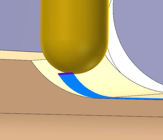
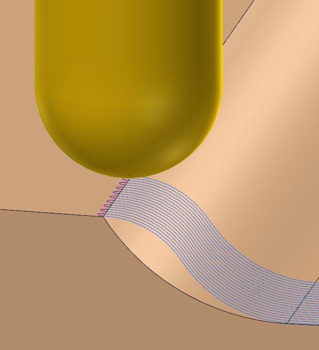
Just a few more months for those who don't want to use Beta software... Applications is testing on-machine far in advance of Beta cycle, so I have a different tolerance for risk than most. Need a lot of coffee for red button reaction time during very early builds! Here's some cool examples of reflowing UV's of a surface that didn't align well with an adjacent groove surface, and where the UV was initially a simple grid that caused a lot of unnecessary relinks where the groove surface narrowed at the top end:
-
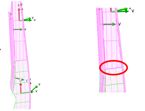
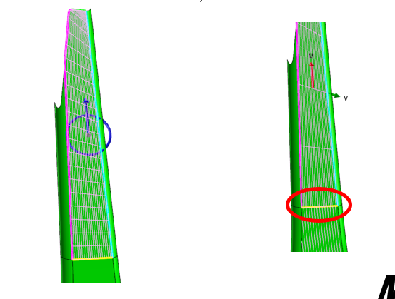
Right- I usually passed it up if I was trying to toolpath more than one surface and the UV's weren't already aligned. Viable in my mind here is viable in terms of time commitment vs result. The 2021 tools allow you to edit the UV grids of groups of surfaces to bring them all in line with each other, and the really powerful new tool is to reflow the UV's of a surface based on curve sets. I've used it quite a bit already to perfectly blend UV grids on surface sets exactly like this pocket fillet loop- something that in the past I would have given up on almost immediately and gone straight to Morph- sacrificing the clean motion of Flowline just to get a path without major geometry creation/edits.
-
There are some cool new Reflow UV tools in 2021 that would make Flowline a very nice viable path on these surfaces here....
-

"internal Operation ID" In Tool Path Manager
Chally72 replied to b.bixel's topic in Industrial Forum
The idea of internal Operation ID's is that they are never renumbered or changed, and become permanent references tied to that operation upon initial creation. Why do you need to show the Internal Operation ID's to begin with? Typically, these are only leveraged for chooks and other tools that need a permanent key for the operation regardless of if the user reorders it or not. -
I actually misspoke- you can ALSO adjust the projection between a holder and extension within Mastercam as well, by right-clicking on the assembly in the Tool Manager, selecting Edit Projection, and using the same method of CTRL+clicking the parent component. Sorry!
-
You can adjust the projection between a holder and extension in the standalone Tool Manager, but not in Mastercam currently. If you select the parent component in standalone Tool Manager and then CTRL+Drag, it works the same way it does when setting tool stickout. https://www.youtube.com/watch?v=gTVylp7Mo1Y&feature=youtu.be I don't have my 39.5 foot pole to poke the trim comment right now...
-
JoshC is correct- looks like stipple highlighting was turned on on your home setup. A note- Stipple and Glow highlighting options more sensibly reside under File | Configuration | Selection for 2021. Both of these options are on by default right now for the public Betas.
-
Correct- if changing planes while doing rest roughing, setting up the Stock page to directly calculate based on previous operations in different planes can have adverse effects. I attached a simple little example showing a block with a 2D dynamic, a Stock Model based on that operation, and then an Optirough rest rough that references the Stock model. Usually, I tout best practice as modeling your stock as a solid body, and creating a Stock Model operation as the very first operation in your toolpath tree and referencing that solid. This skips Stock Setup stock (under the properties of the machine group) entirely. In this example, though, I wanted to show how 2D Dynamic automatically picks up on Stock Setup stock settings, so I've used Stock Setup here to create the initial stock. Let me know if you have any questions! Stock.mcam
-
Hey Terry, Same here, if you wanted to send me a Z2G. I'll take a look at it and if I can't find a solution, I'll make sure the right people see it. -Dylan
-
Hi MetalSlinger, The short answer is you're free to use whatever toolplane you want if you're using a rest stock model, but plane definition for stock models can be tricky if you're moving toolplanes around and don't understand what's happening to the stock model orientation in the background. If you can upload a file, we could step through how to set it up best for your particular example.
-
Right, which is why we don't know/can't assume this behavior well at the Machsim level if the post isn't hooked up. If head/head, my example 'safe motion' would be a very bad assumption. There were two switches introduced in 2020 in the Simulation section of Configuration- Tool Starts from home position after tool change, and Go to home position on tool plane change, that can now help behavior like this if you take the time to set up home/reference points in each operation, but it's definitely not for the beginner/takes time to first understand, then set up properly for each program/toolpath. I'd rather recommend synchronizing rapids in the control def and giving it that 'free' move, and then taking the time to understand your post behavior during that move for your specific machine configuration.
-
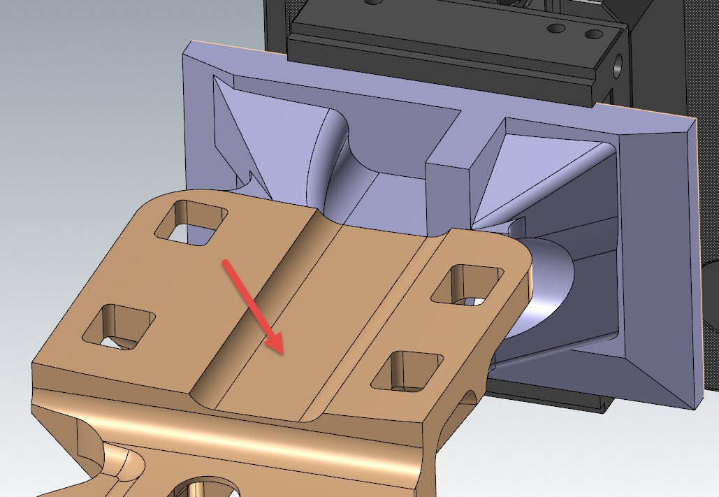
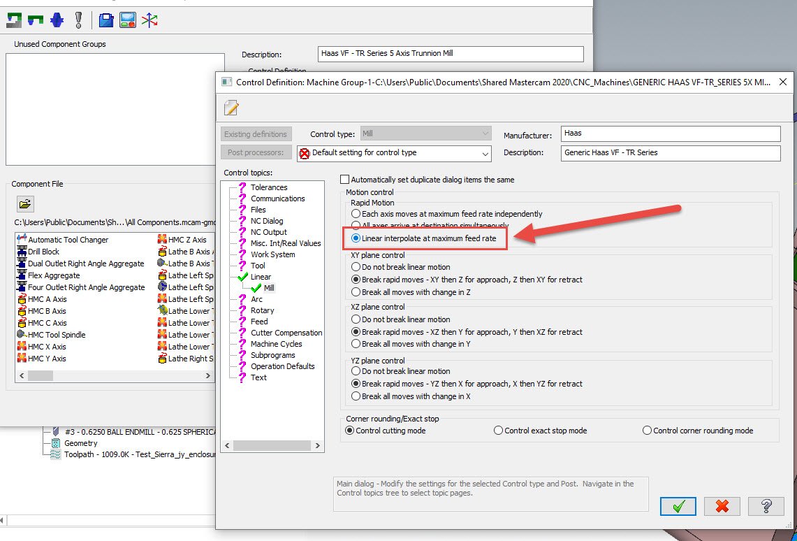
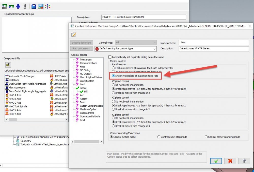
So, transitions like this are difficult because we don't know what the post behavior will be for the transition- (though any good post will retract in Z, then XY, then position rotaries, then preposition XY, then preposition Z.) You'll note that what's happening when the rotary is positioned is that the tool stays at the relative XYZ coordinate of the last point of the previous toolpath, and then you just get a vector change. This often results in a collision depending on where the new rotary position is at. There is a way to get rid of these collisions between plane changes. Go and edit your control definition and look at the Linear page. For Rapid Motion control, change it to "Linear Interpolate at maximum feed rate". The main function of this rapid motion control is to control if your machine has synchronized rapids, but one of the other side effects is that this setting below will allow a 'free move' between plane changes when re-positioning, which removes the machine simulation collision and eliminates the need for a big giant multiaxis link op just to get through a simulation cleanly. If you've modified the disk copy of the control def, make sure to reload it into your local file for the changes to take effect. Also note that this will NOT show dogleg rapids in Verify or Simulation anymore, since we are telling Mastercam that we're now working on a machine with synchronized rapids. Hope this helps!
-
I have the same thoughts on this, and as someone who has never tried to transform-rotate an axis sub, I ran into the exact same tripwire....
-
Just to update- the issue with this wasn't the posting of the axis sub itself, but the posting of a Transform-Rotate of the axis sub, which is not technically allowed. There's a KB article on how to use Transform on axis sub ops without using Transform-Rotate: https://kb.mastercam.com/KnowledgebaseArticle50169.aspx?Keywords=Axis+sub
-
If you can, shoot me an example zip2go that does it and I'll take a peek.
-
It's a result of tolerancing. The verify model that you're seeing is a faceted mesh in the background, and on smaller arcs, there aren't as many facet faces to make up that arc as there would be on a larger arc with the same tolerance/facet size. As JParis said, you can tighten up the tolerance to increase the number of facets on the mesh, but calculation time goes up commensurately.