Chally72
-
Posts
499 -
Joined
-
Last visited
-
Days Won
32
Content Type
Profiles
Forums
Downloads
Store
eMastercam Wiki
Blogs
Gallery
Events
Everything posted by Chally72
-
Hey Mike- There were improvements in posting times in 2019 Update 2 to avoid potential *near endless* loop scenarios. If you install Update 2 and still have an issue, please feel free to message me with an example zip2go.
-
I believe this is dependent on your post being able to handle this orientation change- Most posts do not give you the ability to force a rotation.
-

Advanced Drill - Wow. Finally. This is awesome!
Chally72 replied to Colin Gilchrist's topic in Industrial Forum
We've drilled with it already here in the manufacturing lab. It's one of the new features I'm most excited to use. No more point to point to quickly get out a quirky drill op! -
Yeah, the 2019 and 2020 behavior is that during pecks, it is feeding full depth for each peck, which means shallow pecks on deep holes for example get the backplot time blown up. I'm happy to say that this is fixed in 2021 currently.
-
The Tool tabs that you get in 2020 upon selecting entities can be turned off if you right click, customize ribbon, go to Tool Tabs on the righthand dropdown, and unselect the Wireframe Selection, Surfaces Selection, Solids Selection, Mesh Selection, and Geometry Selection tools checkboxes. I like to customize them to add/focus them to commands I commonly use when working through multiple actions/commands on a single select set, and I find it saves me time, but for those who don't like or expect the ribbon to change when working in "Object->Action" flow, you might want to turn them off.
-
Backplot VCR bar above the graphics window
Chally72 replied to Threept82's topic in Industrial Forum
First step- is 2019 still set to use the dedicated graphics card and not the integrated graphics? You must force use of the dedicated graphics card for the Mastercam .exe in the Nvidia (or other) control panel. Your IT guy should know how to do this if you're unsure of how to verify. -
Example on Stock Model use and transforms for Tombstones
Chally72 replied to Chally72's topic in Industrial Forum
Thanks, you too Colin! -
Example on Stock Model use and transforms for Tombstones
Chally72 replied to Chally72's topic in Industrial Forum
Sure, and for that kind of file/process I'd revert back to Pmeshes and unlink setups to some degree, because at that point associativity can become more of an anchor than a help. The fact that solids exist at world top is the key thing to understand here when trying to expand from single part setups to multiple vises, simple tombstones, etc, and if you've never done it before, you might not even know that it's possible. -
Here's a thread I just posted, with a file and video of one way to approach tombstone stock models:
-
Example on Stock Model use and transforms for Tombstones
Chally72 posted a topic in Industrial Forum
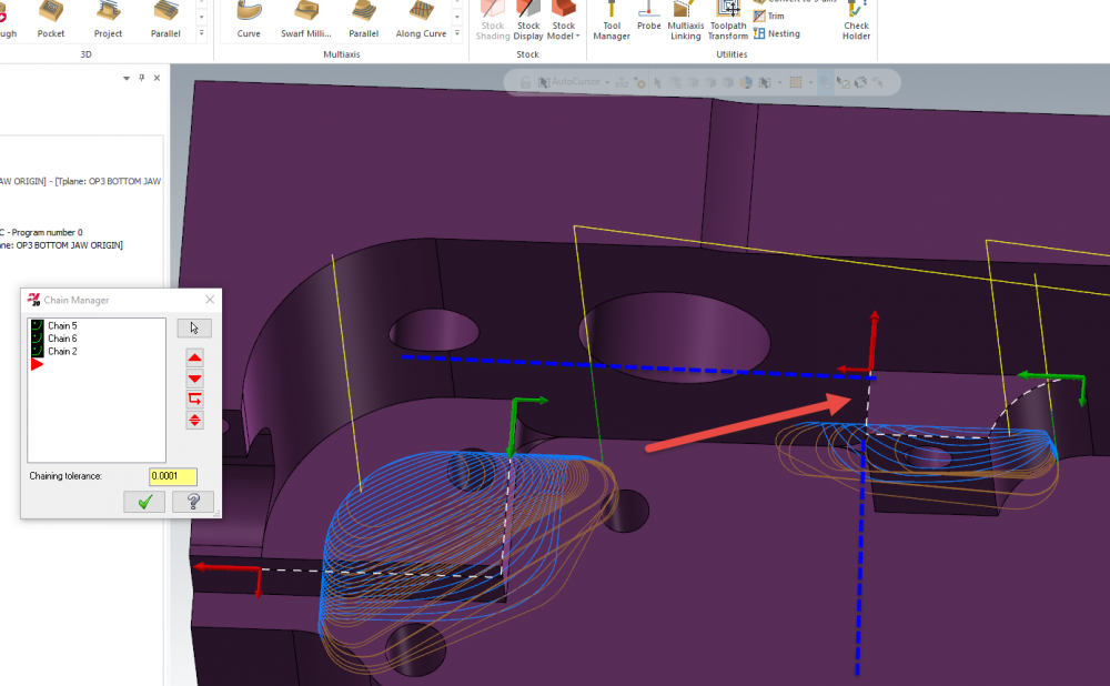
Hey guys, Because I've seen this question a few times and because this is so difficult to explain, I thought I'd make a video on dealing with tombstone machining and in-process stock models. Linked below is a video showing one method of tombstone programming, wherein we use a single solid body as stock for all tombstone ops, and transform the in-process stock models across different faces of the tombstone. Attached is the file from the video. The resultant NC files utilize different offsets for each individual tombstone part instance, and everything is associative- no PMesh usage. The WCS for each operation is also not tied to the stock in any way. I hope this helps expand upon one way of doing tombstone programming! Tombstone Stock Model Transforms.zip -
As mentioned, the plane will usually be Top. Note that the below all applies to Stock Model Operations, and not Stock Setup. (Which I often completely ignore for mill programming.) If you're using a solid body as the stock for the stock model, always use Top for your plane. This is because all bodies that exist in the file are considered to be in World Top, and the solid body is already likely rotated/translated into position around your part, so you do NOT want to apply a translation/rotation by changing planes. You can do some trick plane changes in subsequent stock model ops to then rotate that stock model around to mimic if you were flipping the stock to a second vise, or rotating about a tombstone, but this is difficult to visualize. I recommend not adding source operations and playing around with just changing the planes in the stock model op and regenerating to understand what the rotation is doing. Programming best practice (excluding tombstone machining or vise flips with things like dual vises where you want to see both orientations at once) is usually to keep the part model/stock model in one orientation in space, and 'rotate' the fixturing around it as necessary to mimic setup orientation changes. With this in mind, and starting from a solid body that you'll be using as stock, always use Top for plane orientation. Hope this helps expand a bit on plane choice reasoning for Stock Model Orientations!
-
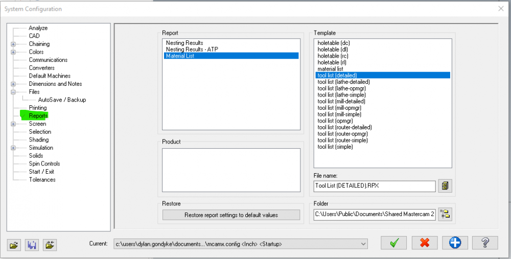
By default, the templates to create these reports live in C:\Users\Public\Documents\shared McamXXXX\common\reports\ (where XXXX is your version) for 2019 and under, and C:\Users\Public\Documents\Shared Mastercam 2020\ for version 2020. If you had these changed to read from a network location, you probably have to change them back by going into FILE | CONFIGURATION and changing the folder path locations on the Reports tab. See image below:
-
I don't have anything as old as X7 installed, but simply regenerating this path with no changes, in 2018 and up, gets rid of this hump.
-
Some reference info- Air region extent is 4x tool diameter. I imagine overlapping region trimming is tough because we have knowledge of only the input chains, and then each region would have to be cross checked against every other region and some intelligence applied to the result. I'm sure this will see many improvements in the future- the ability to add multiple air regions was just introduced, and the functionality will continue to evolve release to release. For now, giving the path a little more knowledge of surrounding geometry is enough to get a good path.
-
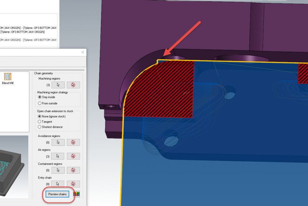
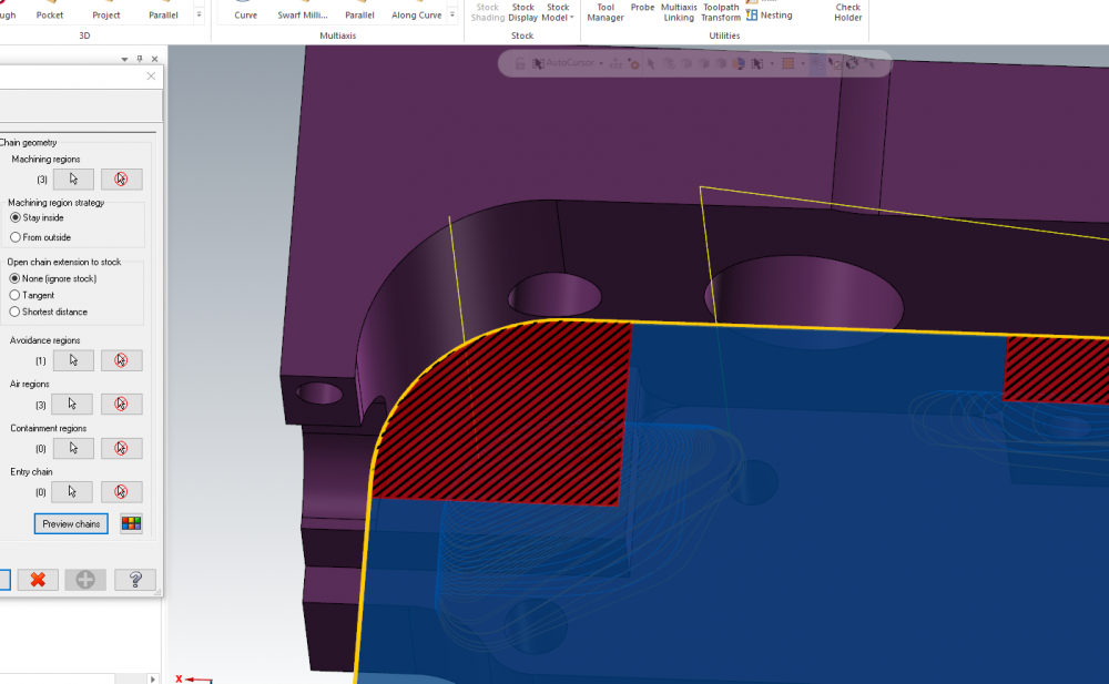
What is happening here is that there's a sliver of air region from the extension off of the middle jaw island that exists beyond the lefthand machining region: Air region extents are automatically sized based on the diameter of the tool selected, and that sliver is being created as part of the air region extents of this chain, perpendicular to the chain edges: Since the toolpath has no knowledge of any geometry except what we're feeding it for chains, it sees that sliver as a valid air region. A solution is to simply add the top left jaw face as an avoidance region to eliminate the air sliver, which gives you this: The ability to add multiple air regions also adds quite a bit of complexity in how overlapping regions are dealt with, so avoidance regions start to become more necessary to control motion around and between the desired areas. Hope this helps!
-
If the uneven bands are areas where the tool is changing tilt to get away from the walls, you needn't worry- the displayed path is showing the tip position, not the tangency contact point. Thus, when the tool tilt has to change for avoidance, the displayed path will show a widening or narrowing gap even though the actual scallop stepover remains equal. Verify results should give you a good idea of the final surface condition if you have concerns about the finish in the areas with tilt.
-
What is your toolpath tolerance set to? Can you post the file?
-
Surface High Speed (Area Roughing) not cutting to bottom
Chally72 replied to saltedfish's topic in Industrial Forum
In the transitions page, have you zeroed out your Skip Pockets Smaller Than value? Posting a file with example path would allow us to provide some focused replies. -
The processing time being extraordinarily long is a good clue that your planes are probably not correct in your stock model operation. The stock is likely sitting right where the tool/holder pass through, and that starts to cause major stock calculation headaches when it results in things like driving the holder through the entirety of the stock body at odd angles. No need to let it run all weekend, especially if you know that a similar stock model generated in 2 minutes- stop the processing and then take a look to see what's wrong with your planes. A good sanity check is to create the stock model with your plane setup, but without applying any Source Operations to make sure that it's starting in the position and orientation you actually want. Then you can go back in and add Source Operations back in- maybe even one by one, allowing you to diagnose if a particular operation is causing a stock model calculation hang. It would be helpful if you could post a file that shows how you're setting up your ops and stock- even if it's on a simple sample rectangle- so that we can provide you specific feedback on what you're doing.
-
I believe Terrance's issue is that he has machines that have perhaps been migrated, and the files physically exist in the folder, but do not show up in the machine list inside of Mastercam when he goes to Manage List to add them to the machine dropdown menu. I've seen this happen occasionally when users manually copy/paste the machine folder structure from an older version, and also if there was a hiccup in migration.
-
This usually occurs when the files are manually copied, for example, from /Shared Mcam2019/ into /Shared Mastercam 2020/ instead of migrated using the migration wizard. When you see this problem, have you tried doing an advanced migration and specifying these two folders as source and destination?
-
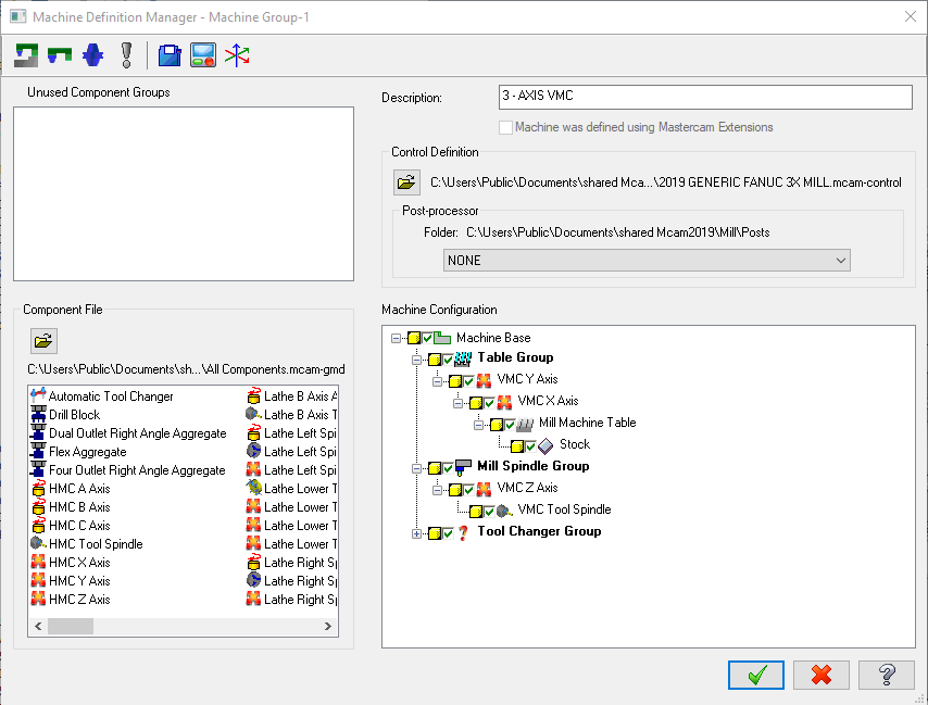
The possible axis combinations in Machine Definition manager are based off of what machine components you have set up, and how you have set them up, in the Machine Component manager- which you get by double clicking on any component in the machine configuration 'tree'. Jim, you can get in touch with me by clicking on my username and then clicking "Message" on the next screen, or by emailing me at [email protected]
-
why does raster rise and fall next to walls?
Chally72 replied to lowcountrycamo's topic in Industrial Forum
It is climbing to avoid contact with the wall avoidance surfaces when the toolpath puts it right against the wall surfaces and it thinks the tool is interfering, be it actual interference based on stock to leave or even a loose tolerancing issue or unseen sliver areas/non-perfect surfaces in the avoid selection. -
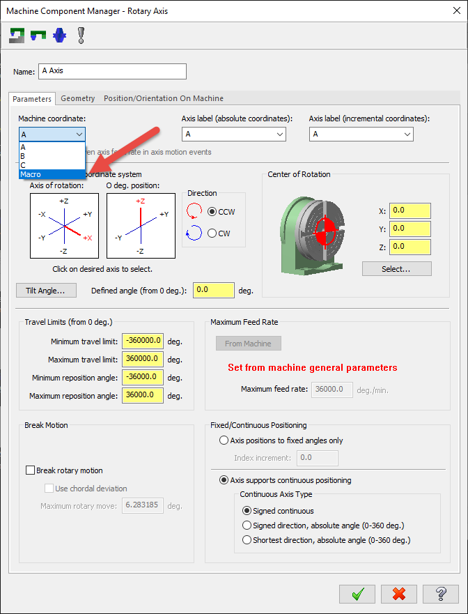
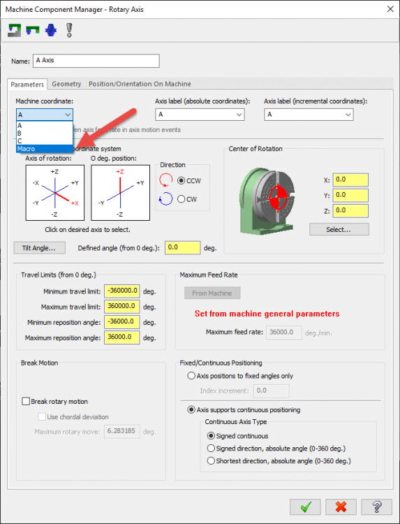
The migration process to 2020 rebuilds the axis combinations available for machine def. In some cases, this will turn off invalid combinations and will require you to create a valid axis combination. Make sure that your axis Machine Coordinate dropdown is not set to Macro for axes used in your axis combos: It is important that machine defs are cleaned up and fixed going forward, as the settings here are driving more and more things. If you're having issues with a machine def, feel free to message me and we can take a look at what's going on.
-
Hey Dan, You don't change speeds and feeds when you first initialize the point toolpath. You first choose your point(s) and create the path, then you can go into Parameters or Geometry to change speeds/feeds or point geometry. For drilling a single hole with a slow entry and then a feed change, I would end up with two point operations in the toolpath manager. One drives the drill from my initial clearance point to the end of the entry move, at my slow feedrate, and the second drives the drill from the end of the entry move to the full depth of the hole, at normal feedrate.