


Chally72
-
Posts
499 -
Joined
-
Last visited
-
Days Won
32
Content Type
Profiles
Forums
Downloads
Store
eMastercam Wiki
Blogs
Gallery
Events
Everything posted by Chally72
-
Hey Corey, that crank program (and also the stock model issues related to it) is a file that I've actually looked at and is a separate issue (with a separate Defect #) unrelated to the fix I'm speaking of here in Update 2. For reference, this is another thread with example on the specific move that Update 2 fixes:
-
A little late to this thread, but 2020 Update 2 has a fix for issues with Verify/Simulation tool diving to center move at the end of a toolpath, which it sounds like is the issue here.
-
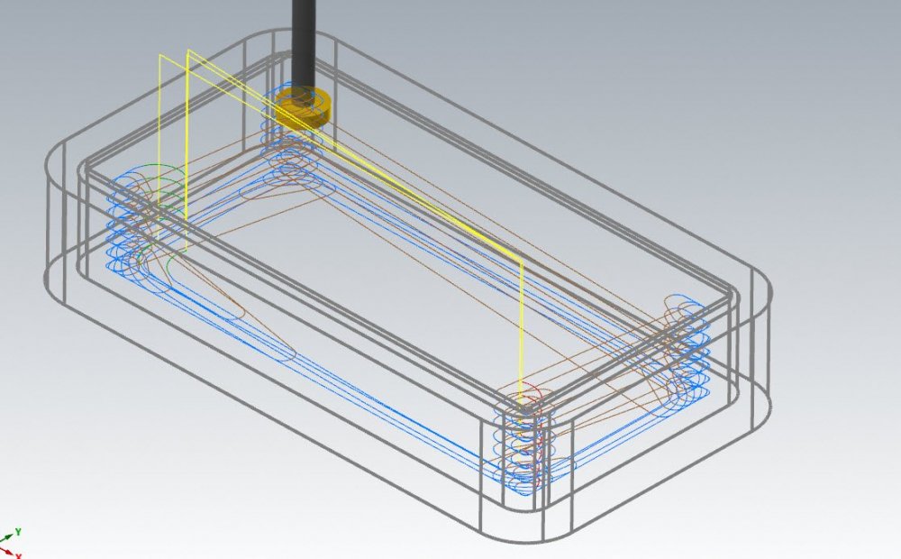
Optirough does not allow undercutting, no. BUT- on a shape like this, where we just have to avoid the lip around the boundary, we could just neglect to tell Optirough the lip is there, set our Minimum depth to be the underside of the lip with a stepdown of the thickness of the slotting tool, and add in large entry and exit values in the Linking page, and voila- dynamic rest roughing with a slotting tool that also properly clears the lip on entry and exit. Now, this is just using a Roughing Tool setting in Stock rest material. If we have a complex stock model, with maybe some variable stock in floor areas, we'd need to somehow remove the 'lip' of stock to allow this method to work correctly and ensure Optirough continues to ignore geometry and stock higher up than the lip. In a case like that, we could use a ghosted facing operation to 'clean' the stock down to the underside of the lip, and then generate a stock model for our Optirough based on this ghosted facing op.
-

Does use feedrate not work in circle mill with 5 axis output?
Chally72 replied to Leon82's topic in Industrial Forum
Thanks for the example. I can see exactly what you mean here, and that it occurs only with safety zones and Circle Mill. It looks like it was already identified as a problem and it is fixed in 2021: As a workaround in 2020, we could do something like Circle mill the groups individually and use a Multiaxis link to generate the exact same safety zone and get the correct feed move between them. I attached an example file. Test_Example.mcam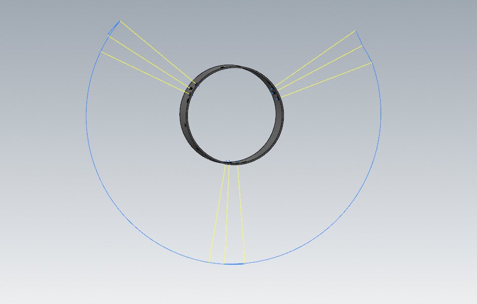
-
If I understand this issue correctly, it's not the normal operation/plane transition motion case that is causing these cuts. As mentioned, this behavior change appeared starting in 2020.
-
Does use feedrate not work in circle mill with 5 axis output?
Chally72 replied to Leon82's topic in Industrial Forum
Right. Can you strip down the file to just the three holes and a single toolpath and post it here? Or perhaps make an example file that does the same thing? -
Corey, I know you posted in the official forum on this one too. I don't have access to that Defect report, but I believe this one is related to stock models and Rotary Axis positioning and the transforms going on in the background. There's no good workaround if you have to use that rotary axis switch right now. Did your reseller provide any more information on the specifics to you, or would you like me to try and dig that up?
-
Does use feedrate not work in circle mill with 5 axis output?
Chally72 replied to Leon82's topic in Industrial Forum
Can you post a file? If you're using Safety Zone, and both your lead-out and lead-in feed moves do not violate (exist outside) the safety zone, then no feed moves will be inserted. This is a little difficult to explain in text form. A simple fix would be to expand the cylinder or decrease the lead amounts to make sure that the feed moves end within the safety zone and thus trigger the insertion of safety moves, which would occur at feed rate if you had that option checked. -
The model is actually directly available from Haas on their webpage for the TRT100: https://www.haascnc.com/machines/rotaries-indexers/5-axis-rotaries/models/trt100.html
-
The Materials toggle is an all-or-nothing toggle, so there's no way to turn Materials view on just for individual solids. The default glossy materials can get a little hard to look at depending on geometry, so sometimes I'll change them all to something like a dull plastic material so that I can still comfortable view them along with the things I need Glass materials applied to.
-
Here's a video on moving parts and stock around a tombstone setup- a little more advanced than what you're doing, but it gives the general idea of the process:
-
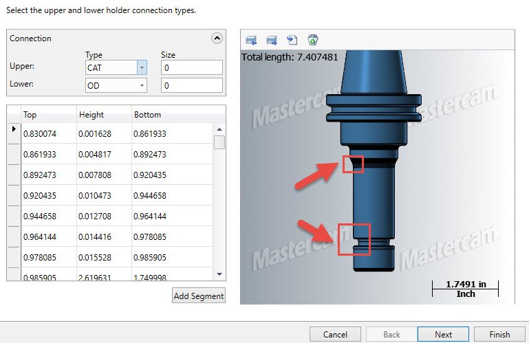
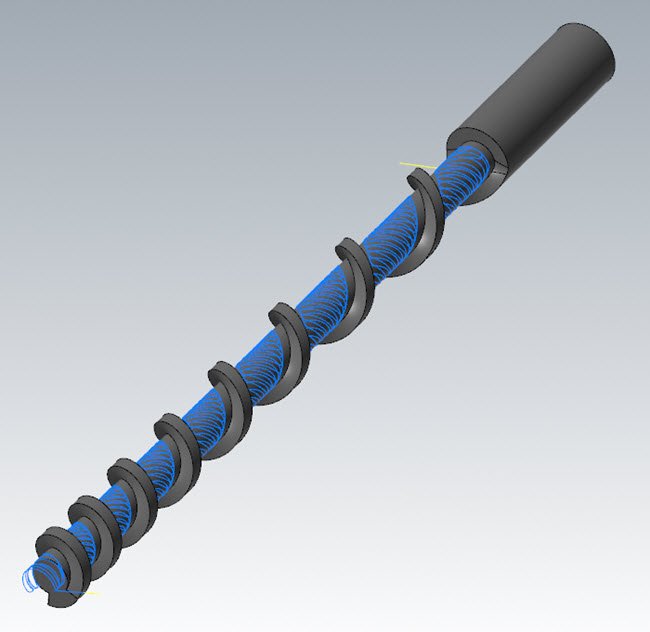
The answer is usually "yes" because of how most tooling vendors supply files for tools and holders. A Ø0.250 ball mill created from scratch in the Tool Manager might consist of 4 entities that make up the cross section to sweep, but download a Sandvik or Iscar 2D DXF and that same straight shank ball mill might have 40-60 entities, with the shank itself made up of a few dozen small linear segments where one line could have done it. These models are often exported en-masse from their native software for these generic online libraries, and leave a lot to be desired. Every added facet in that tool or holder is an added surface that has to be drawn and checked against at every single point in each toolpath, so especially in the case of a complicated holder that models collet nut back angles and radii, you're adding potentially hundreds to thousands of surfaces to the calculation overhead, vs what is normally a 10-20 surface calculation for an extremely clean and basic holder and tool. Here's an example of a holder from a recent customer file where we were doing some complex paths and recalculating rest models quite a bit: This is made up of over 150 segments. Realistically, we don't need to calculate against the lower collet nut undercut because we'll never actually use that for clearance on the part. Similarly, the upper gradual radius that consists of 20+ segments could perhaps be simplified to a single taper if we weren't cutting clearances that close. So, if we were doing a lot of regeneration and testing and HAD to use the holder as part of the stock model calculation and not flip that "5 axis tip only" switch, (which calculates the stock based on the flutes of the tool only and thus exponentially speeds up calc time) I would create a simplified version of this holder to swap in and use for the operations that the stock model references- which is exactly what I did on this one. Hope this helps explain a bit more about streamlining for stock models.
-
Tolerance and overall filesize of the NCI for the ops? Stock model generation set to "5 axis tip only" in Source Operations page? If you need the holder in the Stock Model generation and cannot turn the above option on, is it an imported holder with a million segments to represent radii/etc you don't need? Can it be simplified? Same question, but for the tool- is it geometry linked to a level? These are probably the most common causes of massive generation times that I see.
-
There's a few ways to do this. Method 1. Quit CodeMeter. Go to C:\ProgramData\CodeMeter\CmAct\, delete the 128-XXXXX files, and restart codemeter. Method 2. Quit CodeMeter. Go to the Start bar and type in CodeMeter Command Prompt, and open that application. A Command prompt session will now open. Type in: cmu32 --delete-cmact-license --serial YOURLICENSE#HERE In your case, you'd change the end to 128-14111163, then hit enter. Repeat this step for 128-14122080. Hope this helps!
-
As long as they stayed at a Holiday Inn Express the previous night. For those that might not have seen it, here's a very general video of the UV stuff in 2021: https://www.youtube.com/watch?v=pSBibuV6TO4 Generation of Flow is unchanged from previous versions. Single surface toolpathing is always nice and snappy.
-
Ease of use is a big reason I stay away from Flow paths and other UV based paths as well, and we've got some new surfacing tools to start allowing easier surface manipulation for this type of thing.
-
Mastercam tutorial on programming a part, start to finish.
Chally72 replied to SSS824's topic in Industrial Forum
Have you looked at any of the Titans of CNC free training material yet? They already have a large collection of nice videos guiding you through end to end programming of parts including stock flips etc: https://academy.titansofcnc.com/series/titan-1m/mastercam-program-the-titan-1m More are added every week, and more advanced content is in the pipeline. -
Had an older coworker that disliked rock and roll, and someone changed his Outlook new email notification sound to be an entire AC/DC song, and he couldn't figure out how to change it back. Suddenly we all found things we just had to email him about.
-
The stuff on the Tech Exchange is what we actually cut the parts with in the manufacturing lab, in most cases. The exact tools, feeds/speeds/fixturing that produced the parts you download and see in the videos. If anyone browses through, there's also some very cool examples of things that go underutilized in the software, like using axis substitution in a 2D Dynamic path to cut a variable pitch screw on a 4 axis machine without a multiaxis license: https://community.mastercam.com/TechExchange/Parts/19#partTitle
-
Hey Rstewart, The short answer is that the ToolManager.exe, along with CodeExpert.exe and Mastercam itself, must all be explicitly told to use the Dedicated graphics card. ToolManager and CodeExpert will otherwise run into problems when attempting to draw graphics objects on the screen (create a tool or run Millturn Simulation.) The ToolManager and CodeExpert exe's are located here by default: C:\Program Files\Mastercam 2020\Mastercam\Extensions\ See my response on this below thread for more detailed information on how to force use of the dedicated NVIDIA graphics card for these .exe's: https://www.emastercam.com/forums/topic/95322-tool-manager-crashes-in-2018/?tab=comments#comment-1179651 There's an official KB article that includes instructions for AMD cards as well.
-
You'll be seeing a steady stream of these throughout the year- glad they're of use!
- 10 replies
-
- 10
-

-
Hi Sushant- If your laptop maximum screen resolution is low, there will be numerous dialogs like this that you cannot fully see. As Ron suggested, hooking up to an external 1080p monitor is the best choice in this case.
-
Good point that I forgot about, Leon82. In our shop, the tool probe in the VF2 stopped working after a certain time of day every day- the sun was whiting out the sensor. Similarly, the lighting in the new UMC-750's is great, but if angled perfectly (or incorrectly) in a shiny new machine, it'll white the sensor out when the spindle head comes down. Since this gentleman's probe works file for setting tool lengths, this is probably not it, but it's good feedback for people having problems.
-
Hey LA CAMmer, I'm the one that your reseller has been emailing- I got involved last Friday after CNC Tech Support forwarded it to me and we've been going back and forth. I just sent some additional requests to him, but if you can provide me the NC file that you're actually running at the machine, that would be very helpful- it's the one thing I'm missing. (Just a note- he's been on top of it- if anything, I've been the delay in response times since Friday) -Have you reloaded the macros onto the control since you've updated to 2019? Renishaw switched from v2.1 to v2.9 macros and 2019 is when the switch was made for Mastercam Posting. -Additionally, the vanilla release of Mastercam 2019 contained an error with the installed location of probing files, and thus it would default to older Renishaw v2.1 files instead of v2.9, and this causes many issues, but more importantly, you may never see it if you're running only features that didn't change between v2.1 and v2.9. There’s a KB article here on how to fix this, and it’s important to follow it, because if you don't want to do the manual steps noted, doing a patch update instead of a complete uninstall and fresh reinstall with a full update EXE will not solve this issue on its own: https://kb.mastercam.com/KnowledgebaseArticle50610.aspx?Keywords=productivity
-
No sir, not missing anything. Sorry I can't be of more help.


