Chally72
-
Posts
499 -
Joined
-
Last visited
-
Days Won
32
Content Type
Profiles
Forums
Downloads
Store
eMastercam Wiki
Blogs
Gallery
Events
Everything posted by Chally72
-
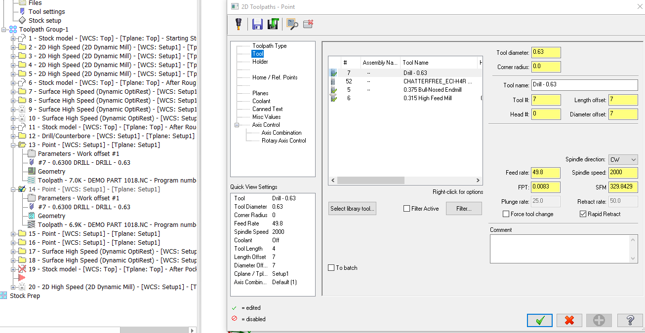
Once the initial points are picked and the toolpath is created, dive back into the parameters and you have quite a few more options to play with:

-
Without making a custom drill cycle, which your reseller should be able to help you with, you can also do a point toolpath and use some wireframe entities to drive the drill around and change the speed/feed at specified depths. This is what I use when I need a hole or two with an entry feed that kicks up when I hit full diameter engagement.
-
For ISO, what is most commonly done for CNC/CMM programs is to do rev control/change logs of the posted code, and NOT the actual file- as Tinger mentioned above. A good ISO implementation of change control will shift the records requirements downstream to the simpler file to manage, and keep you from expending enormous amounts of effort for no reason. Remember, YOU write your ISO document control standards, so take some time to write them sensibly or they'll end up being a pile of rope long enough to hang yourself several times over.
-
When you use minimum vertical retract, are you checking the Output Feed Move box? If not, you're likely running into dogleg collisions on your G0 moves, which of course vary machine to machine. Ocean Lacky, could you post the file or send to me if you'd prefer not to post it here? I'd like to take a look at the path. If the problem does lie at the control, you're on the right track tuning the Min/Max arc filter settings.
-
Just some updated information after looking at the part file in question here- The Collision Tolerance in Machine Simulation (under Info on the menu when a Machine Simulation window is open) is a calculation based on, in part, the Simulation Tolerance in the Machine Simulation settings page. Because the very small scribe tool radius on the etching ops of this part forces that Machine Simulation tolerance to a very small value, and that applies to all operations being actively simulated, we now see all these false collisions for the previous ops. There is no current way to maintain two different tolerance sets for operations being simulated in a single instance of Machine Simulation, and thus the workaround would be to simulate your etching ops separately from the rest of the ops on this part. Also, The Linear interpolate choice will also remove this tool holder orientation swap from the operation transition move in Simulation. In the future, all three options will keep the tool from starting the first point of a subsequent op in the wrong orientation in Simulation.
-
You're likely seeing crashes during the rapid moves that link operations, and what Radical1 mentions is the way to remove these 'false positives'. Be aware though, that now you may have a clean Machine Sim that actually does crash or clip a corner at the machine. The control definition setting "Each axis moves at maximum feed rate independently" is basically showing the dogleg motion that will occur in real life during a G0 move. This will depend on the machine and the acceleration of each axis of the machine. Usually, G0 moves between operations are at a clearance height that is above all part and fixturing features, but if you're down in between things, you have the chance of collision because of this dogleg. Note the Linking Parameters page of a Dynamic Optirough path. When you set the retract strategy to Minimum Vertical Retract, you have the opportunity to convert all rapid G0 motion to G1 motion with a designated feed speed. This is to avoid dogleg crashes that now become much more of a possibility while keeping the tool so close to the part- now all our motion will be linear interpolated at the feedrate specified.
-
Hi Juyong, If you only have Intel integrated graphics, you could try different driver versions and see if you find one that works. Mastercam is not supported on integrated graphics cards, however.
-
The issue here is depth cuts are turned on, with depth set to zero. Turn depth cuts off and you should see it generate/backplot/post OK. This has been addressed for 2020. Edit: They aren't set to zero in your path, but the gist is that yes, depth cuts are causing the issue here, and you're not doing anything wrong. Setting Top of Stock to something other than absolute/incremental zero will also allow the toolpath to generate correctly WITH depth cuts.
-
Just to expand a bit- that requires knowledge of the machine/post, and is outside of the scope of backplot.
-
I would strongly suspect antivirus or user permission issues to be the root cause, especially with an overeager IT department that is doing things like blanket restricting downloads.
-
Using the Push-Pull feature on the Model Prep tab, Ctrl+clicking on one of the 0.078 holes will select all holes of the same diameter, and you can then change them all at once to your new desired diameter.
-
If not a direct file, can you make and share a representative example file with typical paths/geometry/settings that are producing the long regen times? It's hard to discuss anything other than anecdotal suggestions otherwise, and it leaves us without any direct comparisons to make on what times are expected and what times can possibly be improved somehow. Just one example of the possibilities otherwise- a recent thread on the official Mastercam forum noted that surface blend paths were taking an excessive amount of time to generate with a Windows 10 Pro, 64-bit, 32gb Ram, i7-7820X and NVidia P4000 graphics card. Driver issues were a culprit:
-

is there easy way to add a operation separator in
Chally72 replied to mike561h's topic in Industrial Forum
The shortcut Ctrl+E will toggle through the different expanded and collapsed states of toolpath manager groups and operations, and affects either the entire manager tree or just the operations/groups you have currently selected. -
Mastercam Lathe Stock Setup Dialog Box
Chally72 replied to Kenny Machado's topic in Industrial Forum
There was a recent thread with the same issue, located here The last suggestion on that thread was: Is display scaling on? Right click on your desktop and click Display settings; if the value under 'Change the size of text, apps, and other items' isn't 100%, try setting it to 100%. -
The bolts did have threads simplified, but still quite a few surfaces per bolt, and the models for springs and such were pretty heavy. We're talking a 300+MB file here from geometry alone.
-
Just to update after exploring this a little further with Tim- the culprit in the file was mainly hardware- springs and bolts and such- that was accounting for a massive chunk of the load time. Exporting this hardware to parasolid simplifies it in some manner that we don't do with optimize or other tools, and allows us to reimport it into the file and reduce load times to more reasonable levels.
-
Can you post the file, please? I'll take a look.
-
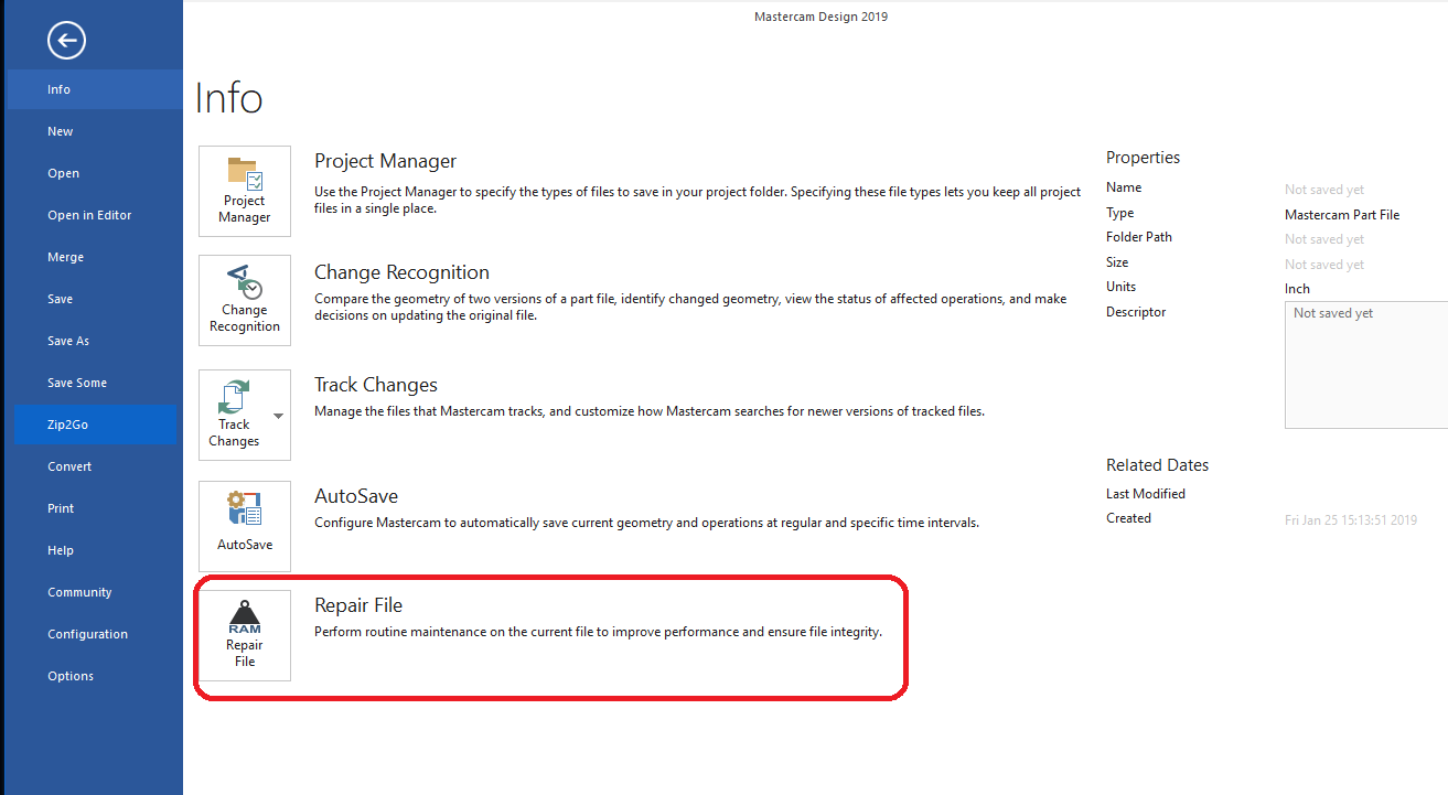
Are you referring to RAM/Repair file? That still exists, on the info menu as soon as you click file...

-
Gcode is saying to open your problem file, export the geometry as a parasolid, then, with the problem file still open, delete your geometry and then use File Merge to bring the parasolid geometry back in. Then, save the whole ensemble.
-
Is the file you're opening actually on your hard drive, or are you opening from a network location? Have you tried deleting or moving your config files and letting Mastercam recreate the defaults, and then attempted to open? (C:\Users\yourusernamehere\Documents\my mcam2019\CONFIG) What kind of solid state hard drive? The words 'SSD' do not always mean lightning fast depending on what was purchased and how it is interfaced. If you are happy with file open times in other softwares though, I would consider this the least likely culprit.
-
If you can post the file, it would help in giving you specific feedback.
-
I'm running a beta not released to the public. Aaron is correct. All is well! (Updated my signature to reflect how I know these things.)
-
I did get it to regen correctly with my version of 2020. So the fix is in, no worries...
-
Setting WCS plane to TOP and regenerating can solve this issue, but something isn't right. Definitely send this through your reseller.
-
Here's a couple of ways to do it: 1. Use a Project Curve 5 axis path locked to 3 axis, window select the wireframe to project, and set Collision Control to retract tool along tool axis when it hits your bolt, which you add as check surfaces. This is the fastest and most flexible way to do this. 2. Use a 3D mill Finishing (Not Roughing) Project path to project your 2D contour op and add the bolt faces as avoidance geometry. A 2D path is never going to have awareness of multiple height levels. You need to step up to a path that recognizes more than just 2D regions projected to a depth if you want to avoid the top of your screw dynamically.