


Codeworx
-
Posts
93 -
Joined
-
Last visited
Content Type
Profiles
Forums
Downloads
Store
eMastercam Wiki
Blogs
Gallery
Events
Everything posted by Codeworx
-
its not uncommon for my files to be 300+ mb and regenerating multiple operations. (lots tied to stock model's)
-
Putting together a list for Santa for a new desktop. Has anyone tired AMD Ryzen for a processor? Specifically the 1900X 3.8Ghz with 40mb cache. Or should I steer clear and stick with i7-7700k/7740X From everything I know about Mastercam and everything I've read on PC spec thread we want Highest Single core speed with lots of Cache and the threadripper meets those criteria, just not sure I want to be the Ginny-pig
-
Transform a Trasnform and add to WCS for each
Codeworx replied to Codeworx's topic in Industrial Forum
I believe you are right, I was hoping to save the extra work . Short term i'm going to hand edit the last 3 positions of each op. Long term Customer is adding a work probe so this problem goes away and I can use a sub with variable offset #. Thanks JP -
Transform a Trasnform and add to WCS for each
Codeworx replied to Codeworx's topic in Industrial Forum
I had coordinate set because the base position is center of fixture(sorry forgot to mention it in original post), so all the positions need different output and different offset. Otherwise I would just use a subprogram. Also when using Toolplane Rotate throws an error in MPMaster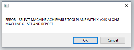
-
I'm either missing something or this is not possible. Sample is mill default but I'm using a MPmaster based post. I am trying to use Transform > Transform and make the output WCS for each position +1. G54.1 P11 to G54.1 P19 I'm able to get the first 5 positions but the last three don't increase (something is wrong in second transform). I know I could make geometry to replace first transform and transform that but my file already has 300+ operations as is and adding 4 operations for each path is not ideal. TIA Transform Transform offset NUmbers.mcam
-
I have mine set to prompt, name groups to meaningful names that make sense for part/paths. This way posted group comment may or may not be useful.
-
X8 prmcode$ for Tool Description
Codeworx replied to Codeworx's topic in Post Processor Development Forum
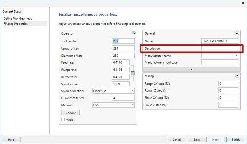
I did some followup testing, You can only pull the "Tool Name", and "Manufacturers Tool Code" from the General Category ( Tested In X8 and 2017). Bummer, I guess I will have my client update his library to have MFG numbers in Description and Crib location in Tool MFG so we can post it -
Wondering if anyone has the prmcode$ handy for X8 Tool Description? My MPPARMATER post doesn't pick it up. I am setting up a Clients post to use a Crib location output from this field. TIA Ray
-
control cut direction of 4th axis rotary tool path
Codeworx replied to lowcountrycamo's topic in Industrial Forum
set wcs to bottom, bottom, bottom with 5x flow gives you left to right. -
RS-232 Machine Monitoring
Codeworx replied to Matthew Hajicek - Singularity's topic in Machining, Tools, Cutting & Probing
cimco dnc-max has the capability. -
Not sure if this is more work or less, but you can use Convert to 5x tool path and set links to "New Links" then you can use 5axis linking between paths. I've done this a few times as I find I could never rely 100% on reference points. You do end up with double the toolpaths, but just another tool in the bag that might help. Ray multiaxis_link_3+2.mcam
-
Try editing the tool then" update all operations" when prompted.
-
same I like the idea of the sit stand alternating. They even make apps or desktop widgits that remind you to change position. I'm defiantly going with the 1 touch preprogrammed setup once I pull the trigger.
-
Np, thats why I love this community, so many different ways to do something and everyone is willing to share their knowledge. I end up using chains alot to drive paths either from chain or to chain. By manipulating where the chain is or the shape of the chain you can control the tool exactly how you want. Need more tilt? put the chain closer, less tilt move it away. Need a zag 1/2 way np add a zig to chain.
-
File was a quick and dirty Sunday sample for the idea, obviously not dialed in 100%. V2 has the Tool control Drive chain moved inside of part to allow the tool to reach the underside. Your sample file didn't have the legs so you would have to add them as collision control check surfaces. +1 on Curve 5, whenever I cant make an advanced path do what I want, curve 5 will do anything, its just alot of work to draw everything up which we try to avoid Ray HOP SKIP AND JUMP_v2.mcam
-
Something like this? https://1drv.ms/u/s!Am1LOI65HdMDgS4BSA3XmOIZx9CR
-
F a gor, G53 is cancel all work offsets on the control. all manuals for f a gor are available on there website for download.
-
excellent product, i cant tell you howmuch time it saves me on a daily basis.
-
Go paperless. Digital setup sheets and tool lists
Codeworx replied to Programinator's topic in Industrial Forum
I set this up at a customer a few years ago. For the pilot project we used Cimco NC-Base(Already owned) on a windows tablet, and also setup shortcuts for there ERP, Drawings library, company documents. Worked well, but after crunching costs it didn't make sense at the time to go with tablets for limited power, function and screen size. In the end we went with a few all in one PC's strategically placed around the shop. If I was to do it again today, i would look at doing thin clients or having access via mobile friendly web client. -
Ben are you running the 34" UW @ 1080p, or 1440p? I am thinking's of making the jump to 34" UW.
-
Default 2017/18 colors, but with Grid changed to black. I found the lighter background was less eye strain, and when your on Mastercam for 8+ hours a day it helps
-
This is brilliant, whenever I ran into stock model issues I always reverted to "save as stl", then reference the STL file. Basicaly the same thing but I hate having outside files referenced and this solves the issue.
-
On Fanuc the machine can only see tool numbers equal to the carousel. Robodrill 1-21, or 1-14 on eco model. You could use any number over 21 as the offset number(your existing tool library) but the Tool call number/position in machine will have to be 1-21. IE: T1M6 (Machine pocket 1) G43 H50 (length offset "tool" 50) G42 D50 (Dim offset "tool" 50)
-
This I always thought it was counter intuitive when the interface was cleaned up moving everything away from the bottom of the screen then they added tabs at the bottom as default.
-
If the Machine models are not available, or you only need to check some toolpaths. A quick and dirty method I've use sometimes is draw the head and add it to your tool holder Assembly. You can only define rounds(which should be fine on your mazak since the head is likely roundish), but it works quite well and Verify will pickup any any collisions if you have your vice/chuck defined inside Mcam. Ray
