cncappsjames
-
Posts
1,240 -
Joined
-
Last visited
-
Days Won
88
Content Type
Profiles
Forums
Downloads
Store
eMastercam Wiki
Blogs
Gallery
Events
Everything posted by cncappsjames
-

Is it just me, or is Tool Manager kinda... lacking?
cncappsjames replied to RecceDG's topic in Industrial Forum
You mean like this; And this?

-
That's the only place I've seen 'em too best I can recall... CMM's. Driving a dot matrix printer that's older than my two youngest kids too (1998 and 2004) ... FTMFW...
-
That thing is a relic. Prolly ought to put it in a museum.
-
I think I've only seen two computers with a parallel port in the last 10 years best I can recall. And they were add-on cards, not part of the motherboard AND they were in QC attached to ancient CMM's. Arrrrrrrrrrrr...........
-
Mastercam V8 feedback...
-
Yeah, stop "moving" your geometry, do like @Colin Gilchrist says and just create a new WCS plane however you want it oriented. Oh, and use Viewsheets. Easy Peasy. I stopped moving parts years ago. Wherever they are in CAD space is where they stay. Then when/if Rev. changes come it's no big deal to pull in the new part and compare models. JM2CFWIW
-
-
can't open pdf files in mastercam 2023
cncappsjames replied to [email protected]'s topic in Industrial Forum
I just pulled in a few PDF's with no issues also. -
There are two ways; 1)Send me the following files from your machine; SYS-CONF.TXT System Configuration Data CNCIDNUM.TXT CNC ID Information (Options, functions, etc…) CNC-PARA.TXT Parameters (axis configuration, center of rotation parameters, etc…) With these files I can tell all the options your machine has and what your available G-Codes are. 2. Press the Offset/Settings hard-key, right arrow soft-key and look for FACT-OFS (or somethign remotely similar) "Standard" is not easily defined. Each machine tool builder adds a specific suite of functions that they make "standard" for their machines. For Example, a Matsuura 5-Axis machine purchased within the last 10 years or so has the following g-codes as "standard"; G00, G01, G02, G03 G04 G04.1 G05, G05.1, G05.4, G08 (covered by G131) G09 G10 G10.8 G11 G17, G18, G19 G20, G21 G27, G28, G28.2, G29, G30, G30.2 G31 G38 G39 G40, G41, G42 G41.2, G41.3, G41.6, G42.2, G42.6 G43 G43.4, G43.5. G43.8, G43.9 G44 G49 G52 G53 G53.1, G53.6 G54-G59, G54.1P1-G54.1P300 G54.4P1-G54.4P7 G61 G63 G64 G65, G66, G66.1, G67 G68.2, G68.3, G68.4 G69 G73, G74, G76, G80, G81, G82, G83, G84, G85, G86, G87, G88, G89 G90, G91 G92 G93, G94, G95 G98, G99 With some additional hardware like 1GB Dataserver and a few other items. That is a "standard" configuration. [rant]A number of our competitors do not make this a standard, in fact they hide it and whan the customer goes to use their machine they find out the hard way (i.e. a a hefty quote from FANUC), then the competitor has the audacity to blame FANUC and the customer that doesn't know any better also blames FANUC and then FANUC gets the bad rap meanwhile the Machine Builder/Dealer comes out smelling like a rose in the deception. All so they could beat another company on price and the customer was not educated enough to compare apples to apples.[/rant]
-
Depending on how the machine was set up the actual machine positions for center of rotation and top of pallet could be #19700, #19701, and #19702 in a FANUC 30i/31i Series Control. To access them by MACRO variable is pretty simple; #900=PRM[19700] #901=PRM[19701] #902=PRM[19702] X, Y, and Z could then be in MACRO variables #900-#902. They will be in mm units so you'll have to convert them if you need inch units. You could do it like this; #900=[PRM[19700]/25.4] #901=[PRM[19701]/25.4] #902=[PRM[19702]/25.4] or like this; #900=PRM[19700] #901=PRM[19701] #902=PRM[19702] #900=[#900/25.4] #901=[#901/25.4] #902=[#902/25.4] Lots of options.
-
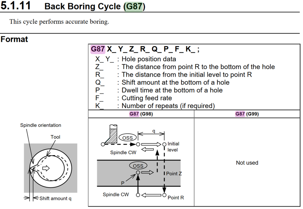
That will depend on your machine's control and your post processor. On a FANUC your cycle is as follows; When the cycle runs you start the spindle at RPM, position (XY) the tool above the hole (G98 initial position), command the G87, then the spindle stops, orients, shifts(Q) moves to R, shifts back to center, starts the spindle, feeds to Z, Dwells (P if commanded), rapids back to R, spindle stops, orients, shifts(Q), moves back to initial position, restarts the spindle. Repeat at next position if desired. HTH
-
@?Mark I need a favor... I'm working on some stuff with a customer and CAMplete for their NMV 5000 DCG and it's just not as easy pull out as the customer or I would hope. Do you by chance happen to have a procedure that you can part with to get the following information out of the machine? SYS-CONF.TXT System Configuration Data CNCIDNUM.TXT CNC ID Information (Options, functions, etc…) CNC-PARA.TXT Parameters (axis configuration, center of rotation parameters, etc…) Or.... anyone else that knows I'd be grateful.
-
In multi-axis cutting there's usually a minimum of 3 things in play BEFORE you even get to running a part on the machine; 1)Surface/Solid/Wireframe creation tolerance 2)Cut Tolerance 3)Point Spacing In my experience (mostly FANUC), both 1 and 3 individually have a bigger influence on finished part quality than 2 does. Tightening 2 and doing nothing with 1 does nothing but hold you closer to what is already bad. HTH
-
Is it just me, or is Tool Manager kinda... lacking?
cncappsjames replied to RecceDG's topic in Industrial Forum
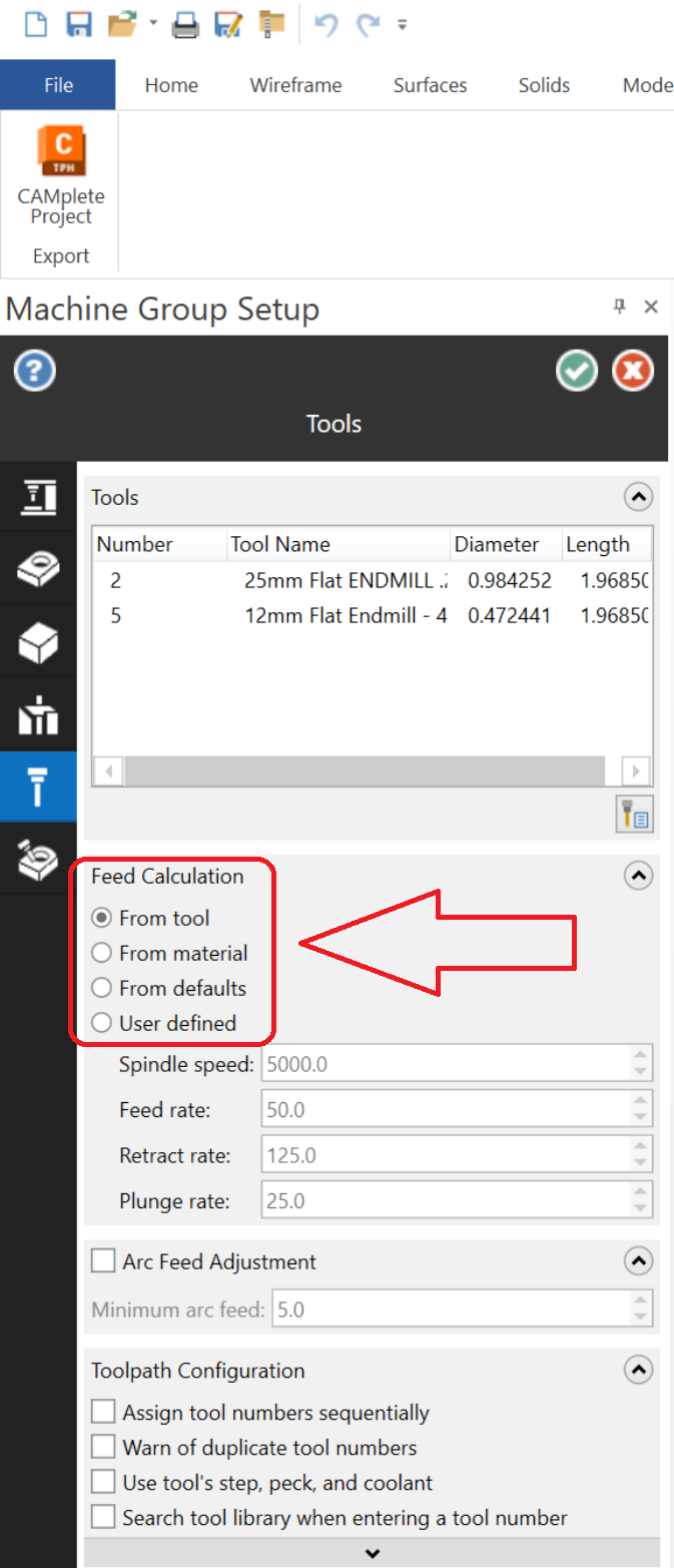
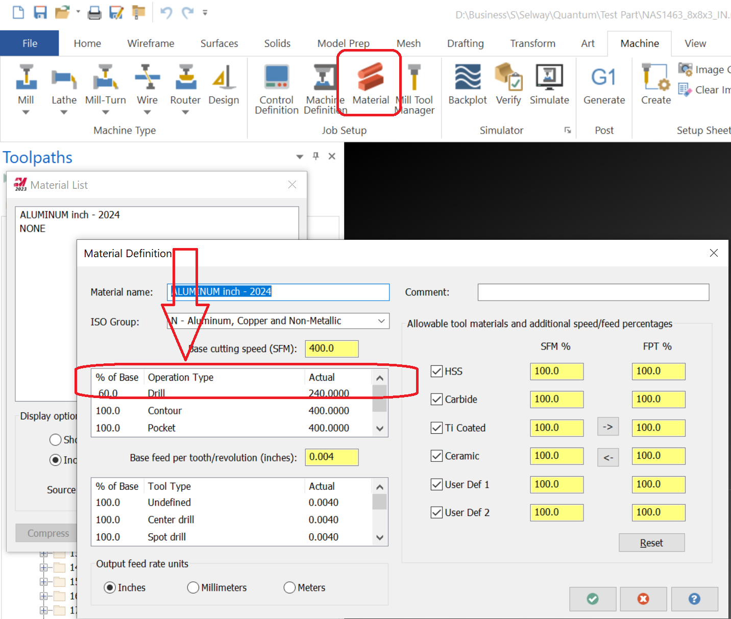
There are two ways to handle S/F with tools. From Tool and from Material. You specify this in the Job Setup. There is far more granularity there. You set up your base/general data in the tool then in material you can do more, by operation type and condition. I don't use material much because generally what I do... it would not help my efficiency. Give it a look. It may help you. -
I just took a scroll through the whole topic... some good stuff in here. Some really good stuff from Tim Markoski (RIP brother...). I captured some of his stuff a number of years back. I wasn't able to get it all. https://www.dropbox.com/sh/kh7kswuqtgdtxv6/AACbR17-y0hbbUV0a0CbrOnka?dl=0 Using the wayback machine some stuff may still be able to be accessed. https://web.archive.org/web/20130611010812/http://www.mtbtech.net/blog.html
- 182 replies
-
- 4
-

-
- custom macro b
- cnc
- (and 2 more)
-
#100=1. WHILE[#100LE60.] DO1 (DO THE THINGS) #100= [#100+1.] END 1
- 182 replies
-
- 3
-
-
- custom macro b
- cnc
- (and 2 more)
-
Do you guys drill out corners where applicable
cncappsjames replied to lowcountrycamo's topic in Industrial Forum
In "engineer's" favorite corner radii... 1/8 and 1/4... metric tools are your friend. 6mm and 12mm respectively. -
Do you guys drill out corners where applicable
cncappsjames replied to lowcountrycamo's topic in Industrial Forum
Rarely. Like never in the last 15 years. -
Feed and motion. And yes, dynamic in Al. as well. I've found I can pull higher cubes AND get more consistent results. Long feed moves like that should be hitting close to 60m/min. in Al. with that kind of available HP. I'm with @JParis... work like that MAX DOC step up if necessary especially with ribs... generally speaking of course. I'll cut 7075 with different strategies than 7050, and different than 6061. JM2CFWIW
-
Yeah.. that's like A LOT of extra work for no good reason. Or, at least no good reason I can come up with. I've run plenty of mult-tasking lathes over the years and NONE had that same number of ops per channel restriction. FOlders for MACROs, settings, etc... that's a little on the cool side I think. As long as it's logical to manage. I wonder what the reasoning is...
-
We won't get a tree for another couple weeks. Thankfully. It's always my job to water it.
-
No workie for me either.... just taking a break from cleaning the pool after the winds blew all kinds of stuff into it and prepping Christmas lights... Honestly I'd rather be working.
-
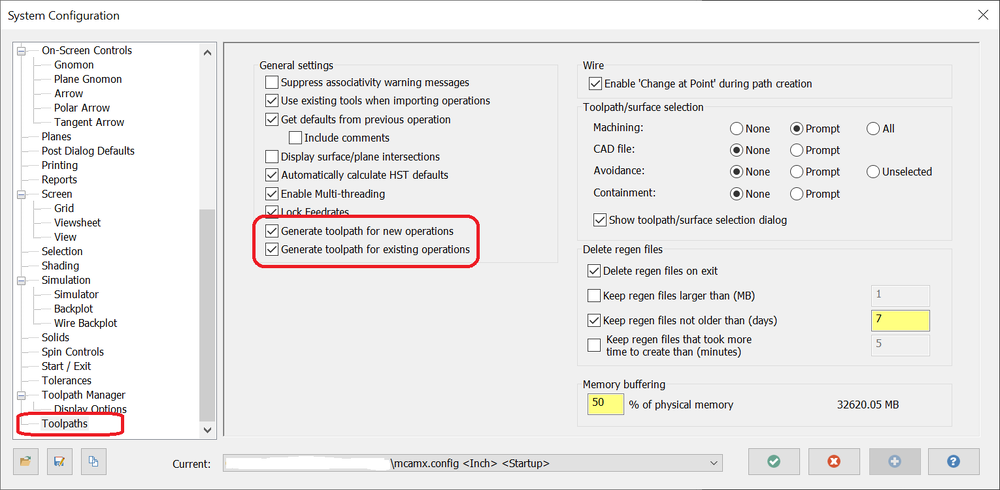
THey could have taken that checkbox out in your version.
-
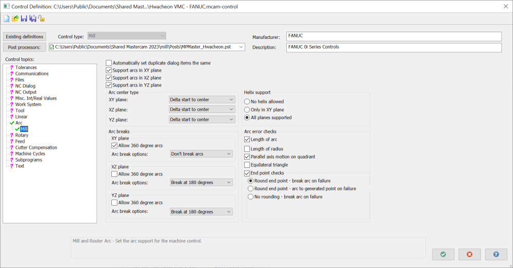
I've got 1 or 2 MC G-Code posts I use from time to time and I only get arc motion on thread mill toolpaths. Perhaps your Arc Settings need to be changed in your Control Definition. Here's my settings.
-
Acramatic 950 Programming Manual
cncappsjames replied to Jing's topic in Post Processor Development Forum
You're probably going to have to pay for something that old. I haven't even seen one of those controls in over 20 years if it's the one I'm thinking of... that is the generation before the A2100 right?