Zoffen
-
Posts
447 -
Joined
-
Last visited
-
Days Won
3
Content Type
Profiles
Forums
Downloads
Store
eMastercam Wiki
Blogs
Gallery
Events
Everything posted by Zoffen
-
This is where something like how NX visually represents depths of cuts with visual cues on screen when selecting toolpath options would be a great addition. It seems like something like this could be useful for many toolpaths in mastercam.
-
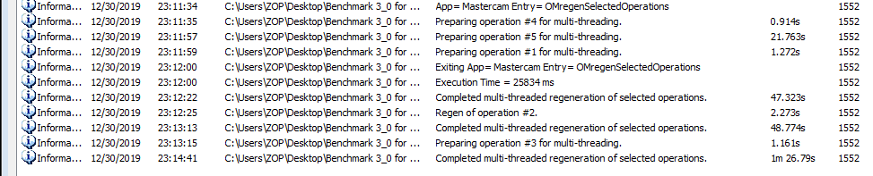
I had it set at defaults...which were 4 threads and normal priority. Im not sure it respects that setting because when you look at my process manager it will show alot more than 4 threads being used. Kinda odd. I will run again set to use all 32 threads and a high priority and report back.
-
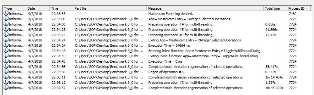
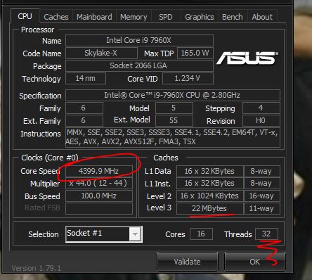
Just reran this in 2020. My 2018 time was 3:57 2020 is 3:07 cpu is overclocked to 4.4ish ghz It's interesting to compare this to g-codes i9-9900. That processor seems to win on tool path generation but with more cores on the 7960X the stock model seemed to regen a bit faster. Maybe it's time to make another benchmark thread that will crunch for a bit longer to really reveal some more useful information. Maybe add some 5ax moduleworks paths with some heavy collision checking into the mix? I have seen those paths use 100% of all cores on some more complex stuff. I wish someone would bite the bullet and build a 3950X AMD rig and run this benchmark.
-
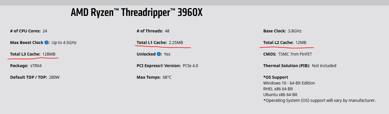
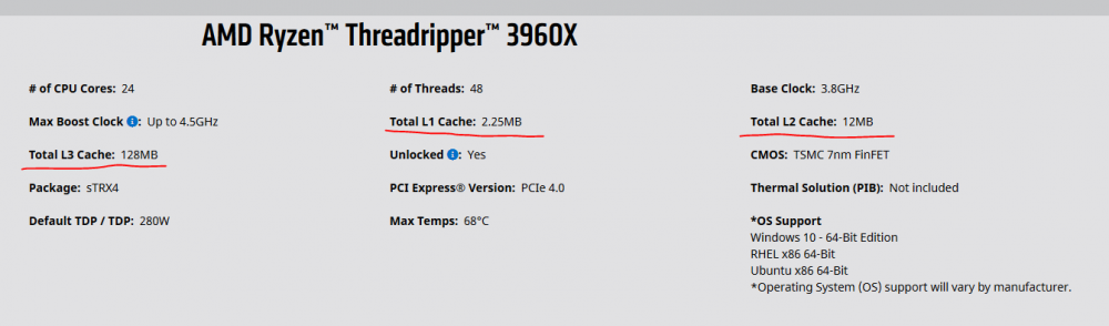
The most interesting thing about the new AMD processors on the high end is the processor cache: I'm really wondering what this will do for toolpath calculation times and overall mastercam performance. The intel 9900k has only 16mb or cache total just to compare.... Any thoughts?
-
You might need to have logic added to the post to handle rotations around Z when the tool axis has not changed from the normal (TOP WCS) z+ tool axis. Most posts will use the tool axis only and not the actualy Co-ordinate system (XYZ) to figure out rotations for the machine and code. In your 180 example the WCS may be different but the actual tool axis is still the same. What post are you using and where did you get it? Hopefully someone more knowledgeable than I will chime in and help. HTH!
-
Maybe its a grand conspiracy with the machine tool builders to sell more parts and service
-

Makino Tool Data Registration (M449)
Zoffen replied to kccadcam's topic in Machining, Tools, Cutting & Probing
If you can set work offsets through the cell controller per job then this is possible. I have accomplished what you are asking on a Mazak Palletec cell. What you can do is set a range of extended work offsets... ie G54.1 P200-300 and use that to "Set" data from the cell controller to the machine for when that job is loaded. Then in your NC code you can grab the correct variable # that is associated to the with the offset you "Set" the data and use that to alter the length or diameter offset per tool or even toolpath if you get crafty. You can even have it altered in the NC code per toolpath and also altered by the Cell Controller. This is a very simplified explanation. If you would like a more detailed one feel free to PM me your number and i can give you a call as this would be easier to explain on the phone. -
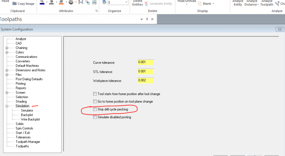
It is located in your config stuff:
-
Here is a link to a thread from a while ago if you missed it:
-
I think you need G54.4 I was under the impression G54.2 does not support full five axis (ie G43.4) and you had to use G54.4. Maybe someone else can chime in....but i have used G54.4 and G43.4 together successfully on a variaxis i-700 before.
-
G10 offset output from Zoller
Zoffen replied to kccadcam's topic in Machining, Tools, Cutting & Probing
I don't have experience with zoller presetters directly.... But I imagine it would depend on how you want to program the regrinds.... If you can output your **ALL** of your toolpaths using cutter comp, then I would imagine that YES you can use the wear offset amount(Radial or Diameter depending on how your machine is set up) and the toolpaths would make a good part. However if you are using a roughing routine that you cannot output cutter comp(HS toolpaths) then you will need to be aware that you will be leaving extra stock for your finish pass as most roughing paths are output without cutter comp and programmed to center line of tool. The only reason you would want to put any value in the Tool Diameter would be if you are programming really old school and programming to part edge, letting the Cutter Comp adjust for the tool diameter. (I would not do this!) It seems like a good happy medium is to use cutter comp to only comp the finish passes so the regrind would make a good part with maybe adding an extra spring pass to account for heavier stock. Or add a semi finish pass with cutter comp and that will account for the extra stock so your finisher has the same cutting conditions. Example: The path is programmed using a .750Dia cutter but this time you are using a .740Dia regrind. Then the Wear value of -.005(Radial Difference from programmed tool to actual tool) will make a good part. I imagine you can somehow calculate this when the zoller outputs the data by grabbing the variable for the Nominal Dia of the tool and using a simple math equation to calculate the Radial Difference from Nominal to Actual. Example: ((Nomial Dia) - (Actual Dia))/2 = (Tool Wear Radial Value) Hopefully someone with some direct experience can chime in as well. Hope this helps! -
Nope im up in bellingham. I might try to make it down to the lunch n learn at gosiger in kent tomorrow depending on the weather. I think i have your number still ill give you a text.
-
Hey Colin! I gave the Contour 3D method a shot and that seems to be the best for what i'm trying to achieve here. I do use the 3D finishing paths but it seems like more and more i go to the Advanced 5ax toolpaths as i am such a control freak! I can usually get what i'm looking for faster with those for simpler things than fitzing around with the HS and containment yada yada yada i just go to what i know works and bingo bango i move on with my life! Thanks for the input and i hope you are enjoying the washington weather!
-
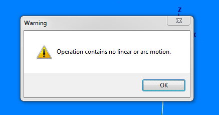
Hello all you smart (and good lookin!) people here at emastercam! I need to arc filter (if possible in all planes G17,G18,G19) an advanced multiaxis toolpath(Locked to 3 axis) that i am using to machine a surface as so: I get a great toolpath but because of machine limitiation (memory and ability to transfer large programs onto the machine - 2005 VF4SS) i need to be able to filter these toolpaths to get them to run smoothly through DNC and or just fit on the gosh darn control. I tried the Arc3d Chook with the following settings .0002 Filter Tolerance .010 Min Arc 1000.00 max arc Buuutttttt it just froze for a bit then came back and yells at me: Does anyone here know a way to effectively arc filter these toolpaths? Thanks in advance for the willingness to help a brother out!

-
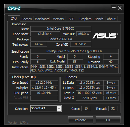
2018: HDD is a Samsung 960PRO Ram is @ 4000mhz
-
Explosion Deburring/Extrude Hone Deburring
Zoffen replied to Zoffen's topic in Machining, Tools, Cutting & Probing
Awesome! The parts the customer has look exactly like the ones on the homepage lol. Thanks for the info. I will look into the cryogenic deburring also. Thanks for all the info! -
Doe anyone have a good source to get one of these processes done to some aluminum hydraulic manifolds? In this case the customer would possibly be looking to buy a unit eventually after proving the process for their parts. Thanks for any info!
-
Mazak Variaxis i-600 G54.4, G68.2
Zoffen replied to Barrier21's topic in Machining, Tools, Cutting & Probing
Haha thats the thing about a good apps guy.....when you find one.....get their cell number and buy them lots of beer!!!! This will pay dividends trust me -
I have the same laptop but with a i7-6920Q/64gigram/M2 ssd w a Q5000M and its pretty good for most things as long as you don't need to crunch lots of stock models or large toolpaths....... but i hate waiting on computers so i just built an i9-7960x @ 4.4ghz with 64gb DDR @ 4000mhz with a single Samsung 960 pro...soon to be 2x in Raid 0.....38" Dell ultrawide on the way....and yes you can run windows7 on these new processors if that is what has been holding people back. Everything is so snappy with this rig i love it. Its driving me nutz now waiting .5 second for the dialogs to popup on my laptop when on my tower it takes 0.0000001 seconds lol! It ran the latest benchmark in 3:23 but we all know that doesn't really show off the performance of a cpu... sorry for the hijack just wanted to brag Max the ram out and add an ssd as ron said...but can't put too much lipstick on it without a full upgrade!
-
^^^^^^^Great idea JLW!!!! For the I-700 i programmed to match ops with 3+2 and full five i would program the part with it in the perfect center position in mastercam. Then at the machine i would probe a feature that is "known" is mastercam and set an offsets i was not using and then calculate the difference from where the part was in mastercam to where the part sits in the machine. These are the values you should use in your g54.4 registers with your G54 still being the COR coordinates. This would allow me very easily to probe an existing part and be able to track the existing datum around the rotaries with no problem.
-
Yes you would think the software would be smart enough to figure this out on its own...i would love to make less geo to do my job! No WCS options on stock models is not a great direction for the function to be heading! That is a very useful feature!!!!!
-
Just as a general Gnomon tip is remember to play with the 2d/3d settings as this has an effect on how the Gnomon behaves. This can be very useful in some situations!
-
I can't answer that question but i can tell you there are alot of fanbois over at PracticalMachinist.com Alot of people seem to like them. Pricing is pretty good too. I'm probably gonna order a few BT30-ER20/ER16/ER11 chucks for a project, i will report back when i get the tools in.
-
Seems like an "interesting" way to finish the part. That pattern doesn't seem to really flow well with the part and seems like when it will run on the machine the up and down z motions asit jumps over the ribs will really slow the machine down...just some more thoughts I would break that up into more logical sequence of finishing...ie....finish wall, then finish floors, then finish rads..... more work but it might run faster as all those retracts will kill the cycle time. Or find a pattern that seems to "flow" around the part better...but on the otherhand if the parts are ok cutting like that then let that dog eat! Always love these moduleworks toolpath discussions....there should be a stickied thread to all the usefull topics involved with these toolpaths!
-
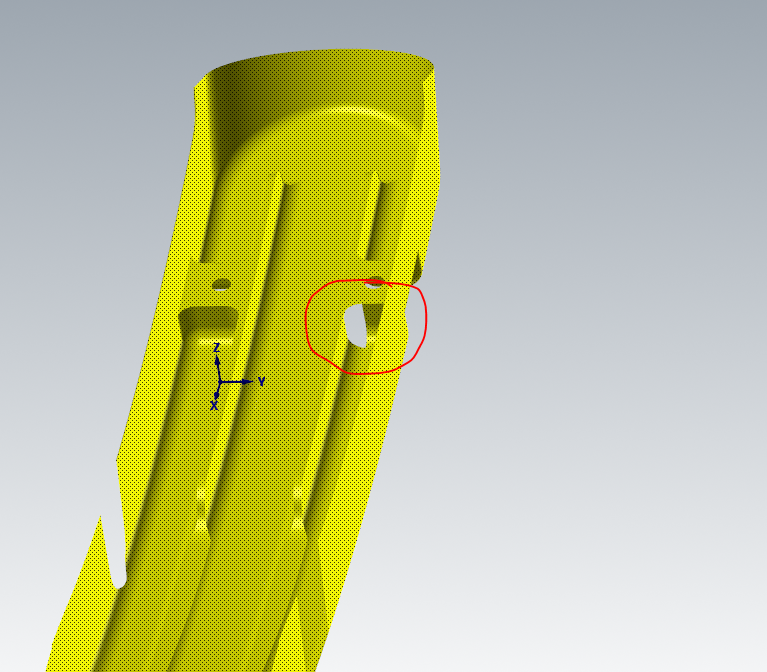
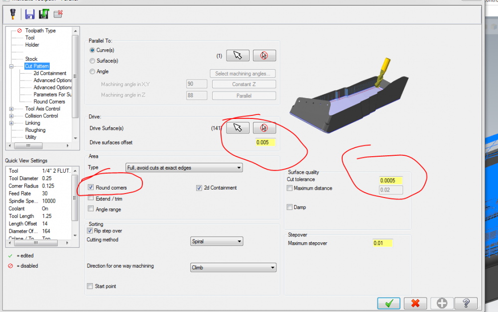
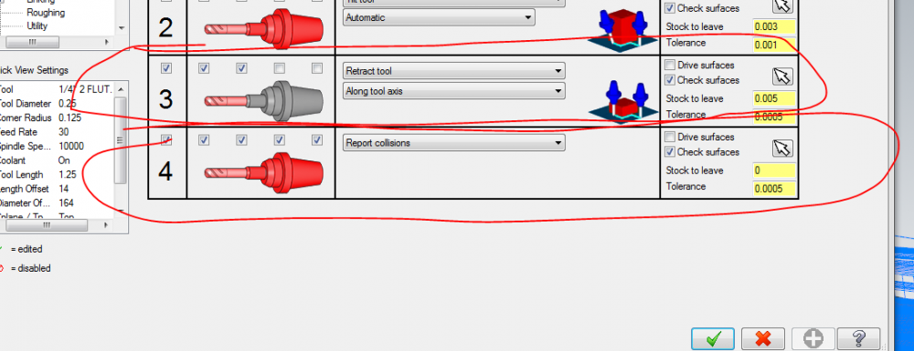
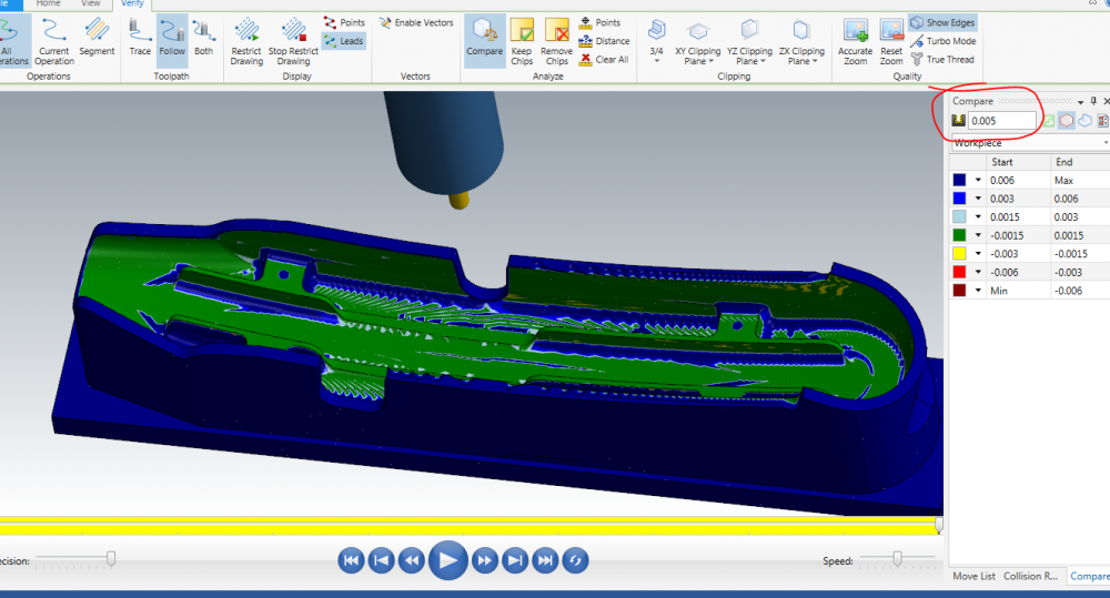
So i'm a little late to the party but got the path to work. I changed a few settings as so plus you were missing a drive surface in a corner, not sure it would have an effect on your issue but you never know with all the black magic going on in the toolpaths. Missing surface: Since this was a semi-finish toolpath i assume you actually want to leave some stock to finish so i left .005, added the round corner option, added a few collision strategies, and tightened the tolerances up on some stuff. Collision: Result with .005 Stock to leave: I had to zip up the file to make it small enough to add as an attachment here. Hope this helps! Stubborn path-ZOFFEN.zip