MoMo1108
-
Posts
59 -
Joined
-
Last visited
Content Type
Profiles
Forums
Downloads
Store
eMastercam Wiki
Blogs
Gallery
Events
Everything posted by MoMo1108
-
Ok.. what you need to do is create a point were you want it to start but the point HAS to be before your geometry hope this helps.. oh ya select that point as your entry point in your parameters


-
4th axis Setup - What is the 'correct' way?
MoMo1108 replied to Newbeeee™'s topic in Industrial Forum
It allso depend highly as to what your doing e.x. im not going to create new plans say for 3 flats 120 deg apart ill do one and transform the others, the same thing for holes. ill do this as much as i can to limit the amount of plans i have. But top view never changes in the wsc just the plans as needed unless its simotanious milling useing multiaxes toolspaths post out as 4th axies then your plans dont come into play -
we use camplete and it works very very well and like everyone else i deff recomend a verification that uses the actual code. as far as the models most repitible palces will give you generic stl files to use but most make your company sign a rights waiver. i dont know vericut at all but camplete you can mod the code line for line if you need to move one point or one vector or whatever and it will show it in real time and allso verifys to the code only
-
Reverse Depth Cuts: How do you pull this off now?
MoMo1108 replied to huskermcdoogle's topic in Industrial Forum
try paralle z if you have multi axes with your key cutter -
as it has been said before programing for that low i would really question if there running a legit copy of mx
-
Reverse Depth Cuts: How do you pull this off now?
MoMo1108 replied to huskermcdoogle's topic in Industrial Forum
do you have a sample or pic from snipping tool .... sounds like paralle z would be best but im not sure what your doing -
well thats what i did here lol
-
just did a simple contour with the right tool def.. yes i know the tool looks rough but you can grind the tool relief at the top how ever you need but just make the tool and contor it other wise you can use a key cutter and use parlle z but that a 5 axes toolpath and can post out as 3 but you need multi axes capabilitys EMASTER.MCX-6
-
radial slot with tru 4th axis or 5th toolpath
MoMo1108 replied to HEAVY METAL's topic in Industrial Forum
i think you will ge better results with the swarf because you can use a smaller tool and sweep the rads instead of running on center and in a sense running into the rads and leaveing chatter and tapper in the rads -
whats your tol. and finish specs .... use and osg sus drill they cut right to size and come in standrd and metric so you can get close to your dia with in a few 10ths i have used these alott there pricey but what isnt
-
very nice ninja, i think it would be less clicks and easer to just finish paralle up the T then accross the T at 90 deg just checking the opposing faces but just my opinion
-
radial slot with tru 4th axis or 5th toolpath
MoMo1108 replied to HEAVY METAL's topic in Industrial Forum
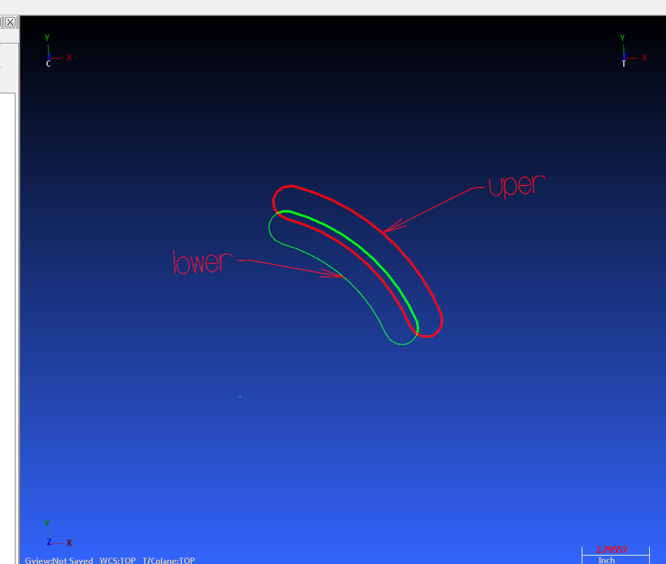
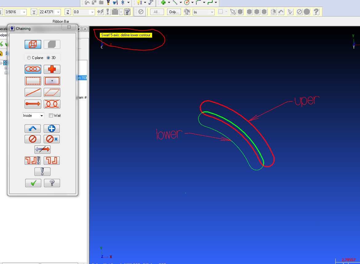
Upper and lower rails are the profile of the feature not the center. If you use the swarf toolpath use chains instead of surface and you will have to offset your bottom rail to the proper depth of your part.

-
or that
-
Its surface contor so i belive it will not go over the top as its a contor.. try scollup starting at center ... not sure if this will work as i cant really visualize what your part looks like eaither ...can u upload it..
-
radial slot with tru 4th axis or 5th toolpath
MoMo1108 replied to HEAVY METAL's topic in Industrial Forum
you can swarf mill it useing upper and lower rails that are synced. i would do it for you but im running x6 so you wont be able to open it -
I cant find any info on this machinist ice ... do you have any or a website or who makes it
-
not very familer with catia please elaborate
-
Would it work in the application of makeing turbins and blisk i.e run a swarf/flank around a blade and modify the vectors for clerance on leading edges or mod vectors roughing out a cavity or hub ? allso do anyone know if they do a 30 day trial or something of that nature.
-
very well put together and i do it the same as ninja only i use it on a layer in the program so its allways with that file
-
Just wondering what everyone thinks of this add on.... it looks very limited as far as 5 axies meaning you can only modify the vectors of curves.... i would like to have the vector mod capability with all 5 axies simotaniouos milling tool paths .... thoughs
-
try m 198
-
From what im told you will no longer have to scale it in x7 fyi
-
here is a simple high speed surface to rough and a simpple swarf ... the surfaces wer all broken and that makes the flow lines go everywere and that what it wants to really follow so i fixed the surfaces and did that you see here ... only did one pocket no feeds speed just so you can see the path .... not to sure why you have your wcs so far off in space why not mcx zeros ? back plot looks ok might need a tweek verify was getting funky but i didnt have time to play with it much.. hope this helps 5X_POCKETS.MCX-6
-
Chris, I have done the syncing nodes and what not and im still getting the devation. it looks as though the surface is concave but then that leads me to ask why can it be done with max5. here is what i have come up with, if you verify it to a STL with a tight tolerance you can see the overcut, you can see the overcut just on the backplot allso. and thank you to everyone helping me im determinded to prove MX can do this and do it accuratly. GENERIC BLADE_1.MCX-6
-
Im not sure what you mean by iso and do you mean impeller blade swarf finish because that uses the surfaces or do i need to use the advance function can you upload an example ... it was proven wrong to me by a point to point analisis that showed the tool devation up to .011