Search the Community
Showing results for tags 'fanuc'.
-
Hello! Is it possible to edit the generic machine post for Fanuc 3X Mill, to have it output every tool change looking like this?: G28 X0 Y0 G30 X0 Y0 M01 T1 M6 M01 G28 X0 Y0 M01 I currently only get the following by default, which does not work for my old machine: ... T4 M6 ...
- 5 replies
-
- tool number
- t1
-
(and 7 more)
Tagged with:
-
Hi everyone, my names liam, I’m new to the forum and after a quick scan I think I’ve come to the right place. Right back to the topic. I have a thermwood c67 twin table 5 axis router (head/head). We had loads of issues with the thermwood control so have just had a full overhaul mechanically and retrofitted a fanuc 30i b plus control. now what I’m interested in is what are the key parameters that must be set to have g68.2 work correctly I think my machine tool builder has set something wrong and is currently off on holiday so thought I’d do some digging. thanks for your time.
-

Peck drilling with right angle head
MIL-TFP-41 posted a topic in Machining, Tools, Cutting & Probing
Fanuc 31i control... Got an application where I need to peck drill with a right angle head, So the drill cycle will run in the Y axis rather than the Z axis. I started looking into a macro for doing this, but then got to wondering if I am just over complicating things So in my head I was thinking I could call up G18, then a drill cycle...so something like this: G18 G83 G98 Y-1. R.05 Q.1 F100. Is it that easy? Or would I have to do something like a G68 Coordinate Rotation while in the G18 plane? Or just stay with the original macro idea? And if thats the case, anyone got a Y axis peck drilling macro handy? Thoughts? -
Hi everyone, We just bought Renishaw Productivity Plus for Mastercam X7. I am trying to make it works on our new machine : machine: AWEA 3016 controller: FANUC 31i The dealer modified our post .pst to make it communicate with the Renishaw post ,renmf for FANUC 31i controller. On MasterCam, I am able to post the program. However, when I am trying to run it on the machine, the program tries to open subprogram that doesn't exist on the machine (see the attached file to see all the program that the program is trying to open. Here's the beginning of the program until the error pop on the screen: O0000 (PIECE TEST-6) (AWEA SP3016) (MACHINE GROUP-1) (MCX FILE - G:\RENISHAW PROBING\PIECE TEST.MCX-7) (PROGRAM - PIECE TEST-6.NC) (DATE - DEC-18-2013) (TIME - 11:16 AM) (T60 - RENISHAW OMP60 - H60 - D60 - D0.2362" - R0.1181") (T4 - SLOTTER 1.00 COURT R1/16 PASSE .125 - H4 - D4 - D1.0000" - R0.0620") (T48 - END MILL 3/8 .375 CARB. FINISH - H48 - D48 - D0.3750") #149=0 (RENPROGSTART) #148=0 (RENPROGSTARTEND) (_RENGCODE_START0001) N100 G00 G17 G20 G40 G49 G80 G90 (_RENGCODE_END) (PRODPLUS_BEGIN) POPEN DPRNT[] DPRNT[PROGRAM*START*PGS] DPRNT[**REPORT*VERSION*1F] DPRNT[**PROGRAM*NAME**O] #1=FIX[#3011/10000] #2=#3011-[#1*10000] #3=FIX[#2/100] #4=#2-[#3*100] DPRNT[**DATE*#4[20]**#3[20]*#1[40]] #1=FIX[#3012/10000] #2=#3012-[#1*10000] #3=FIX[#2/100] #4=#2-[#3*100] DPRNT[**TIME*#1[20]**#3[20]**#4[20]] PCLOS M5 G54 G90 at this line FILE NOT FOUND POP G65 P2109 A1. C1. I0. 1181 D2. E2. H60. M0. Q0. R0.T-999U60.V1.W0.91Z1. Right now I called the dealer where we bought the machine, they said that all the program are in the machine... I called the dealer who sold us Productivity plus and they don't know why it doesn't work... I also wrote to Renishaw and I am waiting for a response. I also check every single program in the machine.. Can anyone help me ? Thanks a lot Cedrick Baker Missing Sub Programs AWEA 3016.txt
- 25 replies
-
- renishaw
- productivity plus
-
(and 6 more)
Tagged with:
-
Hello all, As the title states I am looking for help with running in tape mode on a fanuc 31i control. We are currently having to split programs into as many as 20 separate programs. The machine in question is a mazak vhp-160 with a fanuc 31i control. The hard keys on the panel are about identical to a typical mazak but the majority of the control panel pages and soft keys are more similar to a traditional fanuc control. When I put the machine in tape mode I get none of the pages or soft keys that I would get on either a mazak or a fanuc control. I attempted to use an m198 external sub program call to run part program off usb drive as a sub program but I get alarm sr1807. Code used was : m198 p 13536 Any help or resource anybody could offer would be greatly appreciated. I've read through all the mazak and fanuc manuals and there is nothing about tape mode. What information I found online about external sub programs was conflicting whether a usb drive could be used or not.
-
My shop recently installed a new tos horizontal with a fanuc 31i model b controller, and a 3+2 head. Im wanting to setup dfo to work on a circlular part with several ramps to be cut with the 3+2 head. I want to turn the table the to each ramp location then use twp(g68.2) at a 30* angle to cut the ramps. Im pretty new with the fanuc controller. I looked in the parameters 19700 and found that tos didnt set the center of rotation. I know the location of the center of the table using a test bar but I I am confused on how to enter those values to work with g54.2. My x is 87.9955, z-117.129, and the top of the table is y-.003. Im unsure what a half offset is. if someone would please help me out with this. I thank you greatly in advance.
-
Hello, I require some 5 axis simultaneous programming assistance. I am currently using a Fanuc 31i control on an SNK CMV-80S, it has an A axis head and B axis table as it's rotary axes. I wish to use a tilted work plane (G68.2) and rotate the WCS in line with an error I have previously measured and written to a variable. However on the machine we use a G43.4 TCP function and I can't get the 2 commands to work together. I have attempted using a G43 but that doesn't pick the correct tool length. Is it possible to run these commands together without the G43.4 cancelling out the tilted work plane? Please look at the code below and if anyone can point out my mistake it will be greatly appreciated. G40 G17 G94 G90 G21 G49 G91 G21 Z0 T66109 M06 G90 G54 G68.2 X0. Y353.5 Z0. I0. J0. K#883 G53.1 G43.4 D99 H99 G65<TLCK>M0 M08 M51 S995 M03 G0 X-182.534 Y428.787 A-30. B330. This program will run but it cancels out the G68.2 tilted plane so just runs as nominal part. If I've missed any info please let me know and I'll do what I can to provide it. Thanks all!
- 14 replies
-
- cnc
- 5 axis machining
-
(and 2 more)
Tagged with:
-
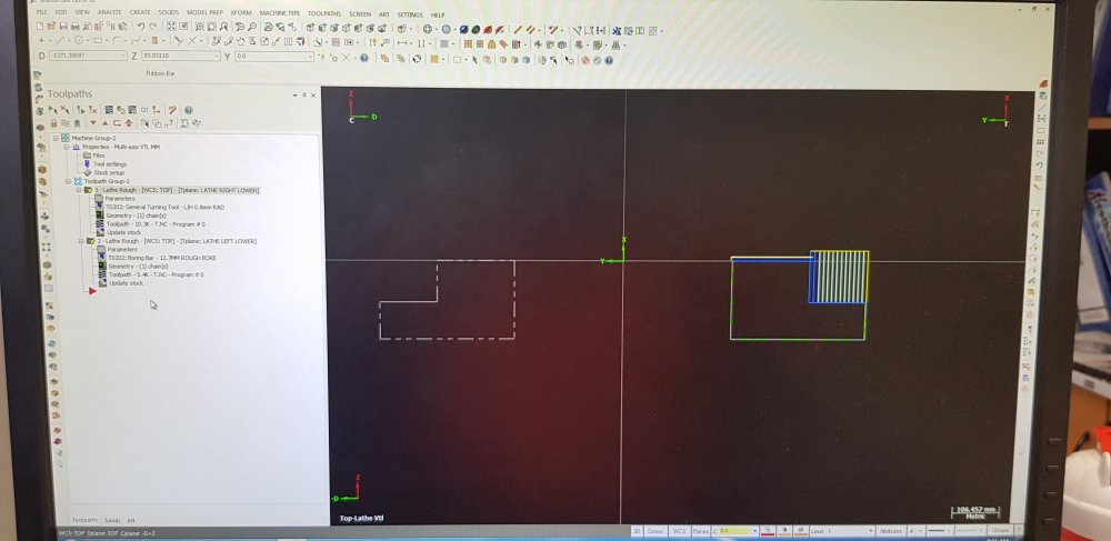
Hi everyone, This is my first post here. My work has recently bought a twin ram VTL & we have been playing round with how best to generate the programs for it. I have been drawing everything in the bottom right quadrant & have been using the multi axis VTL machine type. I have been selecting left turret/right turret in the tool path parameter screen but I cannot get master cam to output two separate programs (one for each turret). Am I missing something basic as I am sure I had this working when I was playing round with it few weeks back. Any help will be appreciated Ryan
-
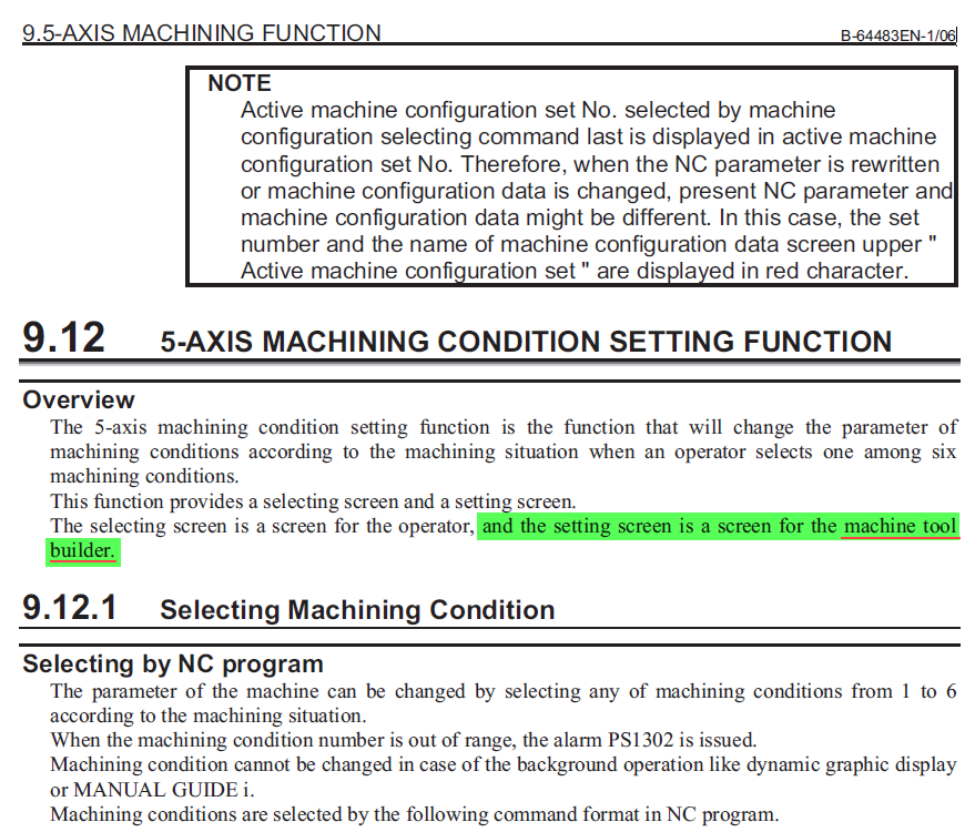
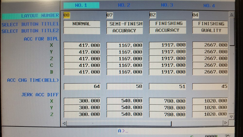
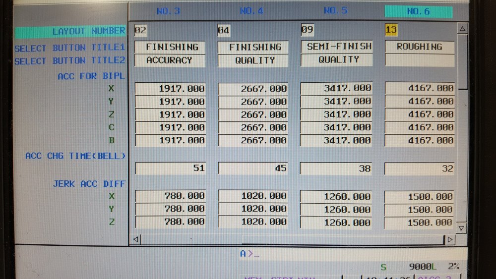
Hi, Do any of you have an idea or can point me to a resource to fill in the Fanuc 5-axis Machining Condition table. It is supposed to be developed by out Tool Builder, Yama Seikie has tried to configure our AWEA FCV-620 but failed in their many attempts at it. It has been nearly 9-months and the machine still jerks when changing direction and does not have a smooth motion at all. See attached for clarification. -Will
- 5 replies
-
- g5.1
- machining condition
-
(and 3 more)
Tagged with:
-
When I press reset it cancels out my tool offset on a FANUC controlled lathe (Daewoo). Does anyone know the parameter that prevents this from happening? Any insight would be greatly appreciated.
- 14 replies
-
Hi everyone, Last week I thrown on a Live tooling lathe with a Y axis. I have never touched a Life tooling lathe let alone a Y axis one. My first part to make is a simple turn part with 2 mill features. A face contour and a cross contour that requires Y axis moves. The cross Contour I have figured out and it works perfectly. The face contour is where the problem is happening, and its post processor related. Our lathes C axis only excepts C0-C360 for absolute commands, Negative call outs Do not work. To do continuous interpolation an incremental call out of H is needed. H can be positive and negative and can be any reasonable number. If you command G0 C360. Once you hit 360 degree's its back at Zero degrees. So, he's what my post is doing. O0000 (PROGRAM NAME - M1808) (DATE=DD-MM-YY - 18-03-17 TIME=HH:MM - 21:44) G20 (TOOL - 10 OFFSET - 10) ( 1/4 FLAT FINISH ENDMILL) G54 N10 T1010 G17 G98 M35 M90 G0 C18.598 G0 X.2461 Y0. Z.5 M8 G97 S2500 M3 P12 Z-.645 G1 Z-.745 F100. G41 X.3594 C28.771 F1622.17 X.3846 C30.65 F1342.62 X.4071 C33.063 F1723.83 X.4263 C35.869 F2000. X.4416 C38.958 X.4529 C42.244 X.4597 C45.653 "" "" "" X.5415 C351.225 F1199.36 X.5088 C354.993 F1583.7 X.4836 C359.654 F1959.21 X.4676 C5.052 F2000. <=== This will send the C axis backwards 354.602 Degrees. Instead of winding up. X.462 C10.878 C49.122 X.4659 C54.038 "" "" "" X.5947 C86.607 F1836.15 X.5747 C92.413 F1856.88 G40 X.561 C98.569 F1968.89 G0 Z.5 M9 G30 V0. G30 U0. W0. H0. M5 P12 M30 % I've gone through the post and found this. #C-axis variables for calculations one_rev : 0 #0 = Absolute positioning with wind up, 1 = Start between 0 to 360 closest direction #MU00004 c_axistype : 2 #1 = C axis winds-up, 2 = C axis signed absolute #3 = index positioning (do not set here, use string) Under machine definition's in Lathe Spindle C Axis I have three options. Signed Continuous Signed direction, absolute angle (0-360 deg.) Shortest direction, absolute angle (0-360.) <=== Current Setting Is there any combo of these settings that will get me what i need? Which is to basically to give me an H incremental move to move the machine into the next 0-360 zone. I am using the Mplmaster post on X9.
-
1,751 downloads
This is a free utility written by MTB Technical Services that generates the cycle data correctly for whatever thread you need. It's especially helpful for tapered threads. It's the perfect companion to the Vargus TT-GEN app and can only help people get more comfortable with G76. Keep in mind that this utility is just a simple little tool for properly formatting the output from the data you enter. If you're cutting anything other than a standard UN/ISO Thread, you'll need to know the proper radial thread depth. The input fields will evaluate expressions so if you have a 4-Pitch API thread you can simply type 1/4 in the input field and it will evaluate to 0.25. The Taper angle will also evaluate the trig needed based on the known taper per foot. For an API Thread with 2" of Taper per foot, you can enter atn(1/12) or atan(1/12) to get the actual per-side angle value. Visit the MTB Tech Blog for more CNC Engineering, CAD/CAM and software development posts.Free -
On the fanuc 21i controller, parameter #3232.1 had a setting to not display my macros. Does anyone know the equivelent for an oi-MD? ( and to save some post response gb space, I know of the #3210 ,#3211,#3202.4 and #3202.6 ones already, I just wondered if they retired the setting or is under another #?) Also on the oi-md , do #3225,#3226 ,work like #3210,#3211 keyword? And what do they protect? I would like to set a password or even a parameter bit(other than what little Johnny can download in PDFs from the net) to either lock parameters through handy offset or in the system. (Little Johnny already knows how to unlock pwe with PKY.) Can I leave PKY at (0) and use 8900 instead of PKY? Peter Smid wrote #3225 & up help protect other important parameters but not go into details and MTB book ,op or maintenance does not show how or that they even exist on planet earth.
-
I wrote a reply to this forum http://www.emastercam.com/board/topic/66927-data-server-ftp-questions/ But wanted to start a new one too. I've got a Makino V55 with the Pro3 control. It has a data server on it. I've configured PC as I think it should be and no luck. The data server puts up a message"incorrect login or password" I've tried to change passwords and login info on both sides to no avail. I'm not sure what I'm doing wrong. I've added exceptions in windows firewall and disabled the firewall. Nothing. I can ping the machine from the CMD prompt on the PC and it communicates there with a 2ms response time. I was asked by the FANUC tech on the phone if I'd tried to ping the computer from the machine. I don't know how. He couldn't tell me. I don't see an option for it anywhere. I've tried formatting the HDD. then added a program out of the control memory for a transfer attempt. Still same error. Any ideas? Bryan
- 4 replies
-
- data server
- Fanuc
-
(and 2 more)
Tagged with:
-
I've programmed a part with 4th axis simultaneous motion that I'm trying to run on a Kitamura HX300iF with a Fanuc 16i-mb controller. The inverse time feed rates are really big (xxxx.xx) which causes the fanuc control to throw the 003 'too many digits' alarm. As far as I can tell, the F register on the 16i-mb has a 3.2 format so anything over 999.99 is a problem. I adjusted the max inverse feed rate in the machine definition to 999.99, is that the best way to control the inverse feedrate so that it doesn't cause a problem for the control? Does anybody have experience with this type of problem on fanuc controls? Thanks
-
1,552 downloads
This is a free utility written by MTB Technical Services for a local Machine Tool Distributor. It makes it easy to generate Engraving programs for your FANUC Controlled Mill. It includes the Macro-B files as well as an intuitive interface for generating NC code for engraving very quickly. Visit the MTB Tech Blog for more CNC Engineering, CAD/CAM and software development posts.Free -
Hi, I am trying to transfer Macros with USB key into my AWEA 3016 using FANUC 31i controller. I successfully transfer 10 programs and when I try to transfer this following program into the CNC_MEMORY, instead of showing TRANFER COMPLETED, it wrote FILE NOTE FOUND. All the other programs that I transfered also looks like this, but this one I can't tranfer it, I don't understand. % O2102 #32=#25 #33=#26 G65P2001 X#1 Y#2 Z#3 G65P2003 A#1 B#2 C#3 D#4 E#5 F#3 K1. Q#21 R#17 S#18 T#19 #1=#[#17] #2=#[#18] IF[ABS[#23]LT0.0001]GOTO01 DPRNT[RAW*POINT*#1[44]***#2[44]***#3[44]] N01 IF[ABS[#15]LT0.0001]GOTO02 #27=#14+#16 G65P2001 Z#27 G65P2001 X#6 Y#7 G65P2001 Z#3 GOTO03 N02 G65P2001 X#6 Y#7 Z#3 N03 G65P2003 A#6 B#7 C#3 D#8 E#9 F#3 K1. Q#21 R#17 S#18 T#19 #6=#[#17] #7=#[#18] IF[ABS[#23]LT0.0001]GOTO04 DPRNT[RAW*POINT*#6[44]***#7[44]***#3[44]] N04 IF[ABS[#15]LT0.0001]GOTO05 #27=#14+#16 G65P2001 Z#27 G65P2001 X#10 Y#11 G65P2001 Z#3 GOTO06 N05 G65P2001 X#10 Y#11 Z#3 N06 G65P2003 A#10 B#11 C#3 D#12 E#13 F#3 K1. Q#21 R#17 S#18 T#19 #10=#[#17] #11=#[#18] IF[ABS[#23]LT0.0001]GOTO07 DPRNT[RAW*POINT*#10[44]***#11[44]***#3[44]] N07 IF[ABS[#15]LT0.0001]GOTO08 #27=#14+#16 G65P2001 Z#27 N08 IF[ABS[#24]LT0.0001]GOTO999 G65P2016 A#1 B#2 C#6 D#7 E#10 F#11 X#17 Y#18 Z#20 #25=#[#17] #26=#[#18] #27=#14 IF[ABS[#32]LT0.0001]GOTO09 #28=#1-#25 #29=#2-#26 GOTO10 N09 #28=#25-#1 #29=#26-#2 N10 #30=0 #31=SQRT[[#28*#28]+[#29*#29]] #28=#28/#31 #29=#29/#31 #[#17]=#1 #[#18]=#2 #[#19]=#3 G65P2013 A#28 B#29 C0 I#17 J#18 K#19 #1=#[#17] #2=#[#18] #3=#[#19] IF[ABS[#32]LT0.0001]GOTO11 #28=#6-#25 #29=#7-#26 GOTO12 N11 #28=#25-#6 #29=#26-#7 N12 #31=SQRT[[#28*#28]+[#29*#29]] #28=#28/#31 #29=#29/#31 #[#17]=#6 #[#18]=#7 G65P2013 A#28 B#29 C0 I#17 J#18 K#19 #6=#[#17] #7=#[#18] IF[ABS[#32]LT0.0001]GOTO13 #28=#10-#25 #29=#11-#26 GOTO14 N13 #28=#25-#10 #29=#26-#11 N14 #31=SQRT[[#28*#28]+[#29*#29]] #28=#28/#31 #29=#29/#31 #[#17]=#10 #[#18]=#11 G65P2013 A#28 B#29 C0 I#17 J#18 K#19 #10=#[#17] #11=#[#18] G65P2016 A#1 B#2 C#6 D#7 E#10 F#11 X#17 Y#18 Z#20 IF[ABS[#33]GT0.0001]GOTO15 #[#20]=#[#20]*2. N15 #[#19]=#14 N999 M99 %
- 5 replies
-
- fanuc
- file not found
- (and 4 more)
-
Hello everyone, I am a mastercam mill level 1 user for several years now and using the search function once in a while but could not find the information i need. So here are my questions. We have a new vertical machining center with 4 th axis The machine is a Hartford HCMC-2082 with fanuc 32i with the G54.2 rotary table dynamic fixture offset ( rtdfo ) function. We are trying to get this function to work but we have no experience with it, and the machine seller doesn't either. The fanuc book also is not very clear. I have read that ithe function is used a lot on horizontal machines, but can it also be used on a vertical machine with the 4th axis when the parameters are set ? Does it use G28 which is on a horizontal machine in the center off the table i think, but on a vertical machine the G28 is a fixed position not in the center of the table so is this a problem. What must be set in the G54 page and what must be set in the G54.2 page on the control. Where do you have to set the workpiece coordinate ( G54 ? ) and where the center off rotation ( G54.2 ? ) We have tryed with G10 L21 Pn P and that does fill the x y z and c coordinate from the program in the rtdfo page on the control. May be a example can make things clear. When we know how the function works we want to use it with mastercam in the MPMASTER post, or is this to complicated. Is there a working fanuc post from mastercam or inhouse or somewhere else. Any help will be very much appreciated. Regards Richard
-
I searched but cant find any info on programming a horizontal from center of rotation versus using work offsets. I have been programming our two horizontals using work offsets for each side of the plate that we have up. For some reason the operators mess up finding the work offsets from time to time for what ever reason. My boss is insisting i start programming from center using no work offsets. What are your thoughts. Our typical work consist of squaring a plate of various sizes four sides with a macro type program. And when we have to put slots, lift holes or short gun drilled lines in i program them with mastercam. I am using top as center then picking the face of the edges for my front, right, back, left offsets which front and back are G54 and right and left are G55. The plate is squared on center of the pallet. I don't like programming from center with no offsets because i have to manually enter a clearance, retract, top of stock and depth. When i normally have to only enter the depth because everything else is entered as a default. The boss wants everything to be monkey proof. He doesn't want the operator to have any responsibility other then hit the go button. I am insisting that we need to at the very least be able to enter work offset.
- 32 replies
-
- horizontal programming center
- horizontal
- (and 6 more)
-
Looking for job, on-line 3-axis mill programming for only 15$/h . Prefer G-code (Fanuc) or dialog (HeidenhainTNC_530). Vladimir
Join us!
eMastercam - your online source for all things Mastercam.
Together, we are the strongest Mastercam community on the web with over 56,000 members, and our online store offers a wide selection of training materials for all applications and skill levels.


