


Orvie
-
Posts
214 -
Joined
-
Last visited
-
Days Won
2
Content Type
Profiles
Forums
Downloads
Store
eMastercam Wiki
Blogs
Gallery
Events
Everything posted by Orvie
-
Does your VTL have a Y-axis? If you can get your Right Angle Head off center, this becomes very easy. If not, there are still a few ways. I am also in Milwaukee. I can stop by if you can't share a file. [email protected]
-
Yes, The price tag will surprise you. It's very reasonable. The simulation is directly tied to the post, so the same engine that generates the NC code is also driving the simulation.
-

Need to figure out how to Create an Entry point/Path in Lathe
Orvie replied to Chaotic5555's topic in Industrial Forum
I just chained the actual groove and used reference points to control entry & exit. -
Need to figure out how to Create an Entry point/Path in Lathe
Orvie replied to Chaotic5555's topic in Industrial Forum
Motor Housing Turning Operation ojs.mcam -
There is no reason to move the models. Create new planes and this problem will disappear.
-
Tapered Helix.mcam
-
pocket.mcam
-
I had a customer that gave me sheet solids often. I think the native file was inventor. I opened them up in Solidworks and saved out as STEP file to fix this. Within Mastercam, I do not know of a way..
-
Robert, you have this tool defined as general turning instead of grooving. Also, Do you really want the control point in the middle of the insert?
-
https://www.sandvik.coromant.com/en-us/_layouts/15/Tibp/Coromant/MyCatalogues/MyCatalogues.aspx/?catalogueId=19695#.W75Q1hOfODE.mailto
-
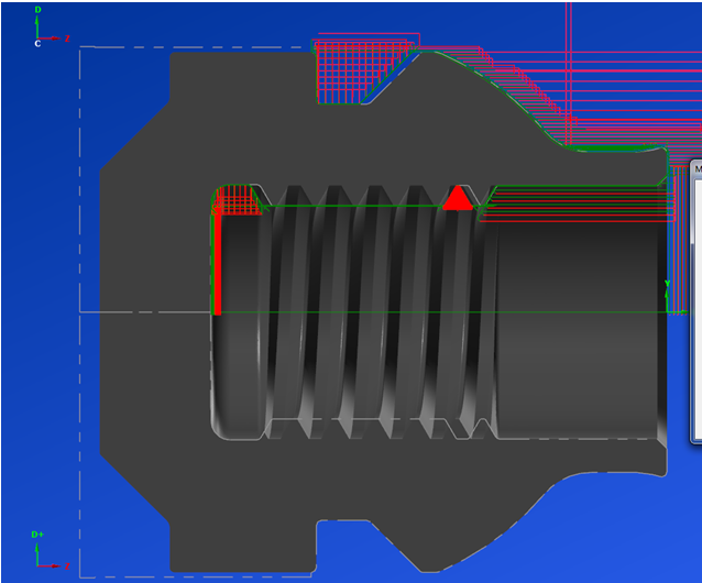
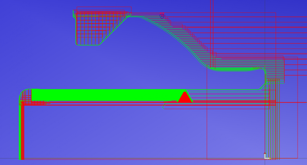
The way I do it, the groove path respects the stock. If I put the geometry in front of the stock, I wouldn't be able to create a finish cycle. This material is usually inconel. By having leftover stock, I can create a second threading operation with smaller stepovers for cleaning up just the walls. Without stock recognition, the finish passes would cut a lot of air and take way too long. I've tried this many ways.
-
I am currently doing this with a grooving tool path. 1. I use “Depth Cuts” so that I only get positioning moves. 2. I make sure that “Groove Walls” is set to “Steps” so that I only get positioning moves. 3. I use “Absolute” for my retract value to clear the threads when positioning. 4. I activate “Dwell Time” so that I have a separate line that I can convert to threading. 5.This only works with a roughing path. Ok, When I post to Cimco, I shift the entire rough groove operation by a given amount so that I position in front of the stock. Then I Replace my dwell line (G4 P1000) with my Thread Z Finish Value & Thread Pitch (G32 Z-5.35 F.500)
-
https://www.sandvik.coromant.com/en-us/_layouts/15/Tibp/Coromant/MyCatalogues/MyCatalogues.aspx/?catalogueId=16327#.W5BeU4-wc9E.mailto https://www.sandvik.coromant.com/en-us/_layouts/15/Tibp/Coromant/MyCatalogues/MyCatalogues.aspx/?catalogueId=18730#.W5BhUA0cL8Q.mailto
-
Sandvik Coromant Y Axis Parting
Orvie replied to Mick's topic in Machining, Tools, Cutting & Probing
I know Okuma is still working on a solution. With Fanuc, there is the possibility of G96 P(reference axis), or G10 L52; N3770 R(reference axis); G11; I am not aware of the process for other controllers. -
-
I've got one too.
-
316L.pdf
-
I have seen those errors before, but in my case it was user error. For me this has only happened when I accidentally turned on M08 & M09 at the same time.
-
Tim also warned to double check ports #16 - #32 for depth accuracy.
-
Pitch in your little gems that make mcam life easier
Orvie replied to jlw™'s topic in Industrial Forum
I've played with it a little. -
https://www.mmsonline.com/articles/vector-programming-eases-five-axis-aerospace-machining
-
stock.pdf
-
looking for a machine builder tutorial for machsim
Orvie replied to danielm's topic in Industrial Forum
-
I have heard good things about Interflux from Northwood Designs. http://www.metacut.com/Products/InterFluxNutshell.htm
-
Absolutely!


