Chally72
-
Posts
499 -
Joined
-
Last visited
-
Days Won
32
Content Type
Profiles
Forums
Downloads
Store
eMastercam Wiki
Blogs
Gallery
Events
Everything posted by Chally72
-
While sliders in the toolpath side of life are generally avoided for a number of reasons, it's a good thought assuming that you have a toolpath that you can make react in a proper manner to the changes, and I can tell you that a lot of the ideas here are very similar to things that have been put up for discussion on this topic. This isn't my area though, and I'm just commenting from a user perspective on what we use and how we teach to get around this.
-
That'd be tough to pin down for the same reasons it's tough to recognize at a toolpath calc level- and if we can recognize a sliver, why not then go out and fix it? But definitely, we want to recognize this before the user has to take it to Verify and see something that is immediately going to be a problem on the machine. And yep, referring to just the technology side, the slivers themselves are the problem that anyone doing this style motion needs to overcome. If the software weights or prioritizes the echo shape over staying in-cut, then the risk of slivers is greatly reduced, but the motion is much farther away from true "dynamic" or constant-engagement motion. Since the latter is impossible for a user to "Program in", but the former can be "programmed out", I think starting with Dynamic motion and then tweaking the path to adjust behavior gives the best chance of satisfying all aspects of a cut. But yes, that doesn't assuage me much when I'm sitting there trying to path around that sliver that just snapped my tool!
-
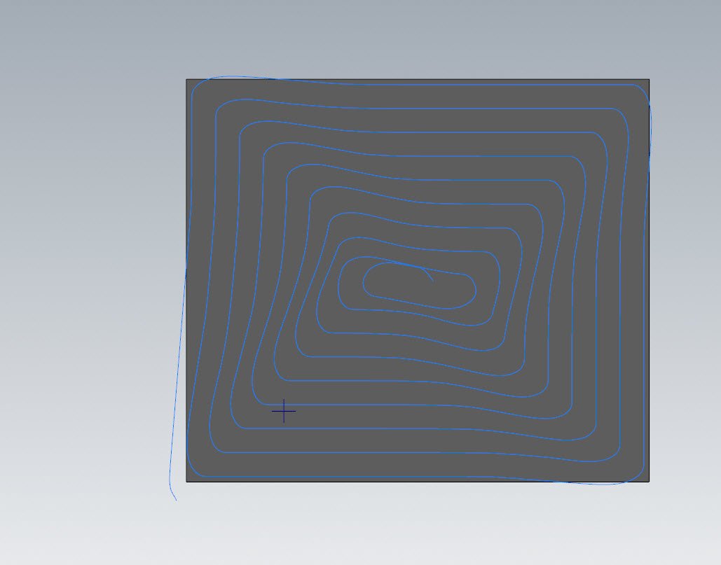
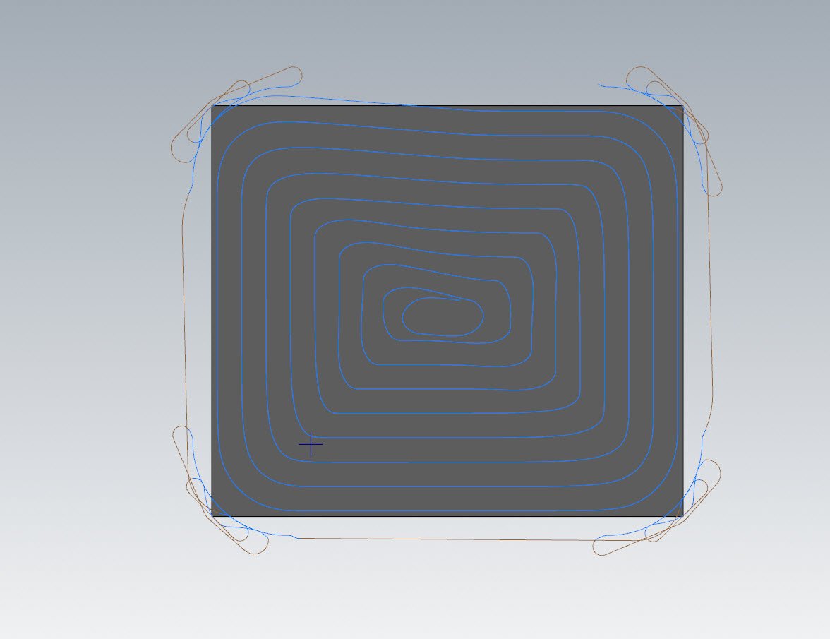
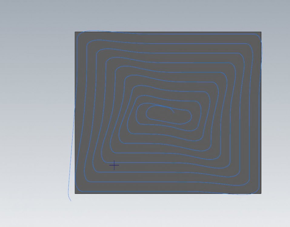
This is a problem inherent in every package that uses dynamic-style motion, and it's a tricky one to address. At some point, you are asking the path to break with its directive of constant cutter engagement to deal with the end result of the toolpath echo near the center of the part. The first problem to address is- what constitutes a sliver? A certain length vs width ratio? Acute corner angles under a certain degree mark? A certain burr height the tool might push? Should the tool engagement be considered in determining a 'sliver' to avoid? The answer is really- all of those along with a few other variables. Roughing of remainders that are fine at 0.5" of flute depth become tool killers at 3" depth. Fine stepovers with certain corners become tool killers if the stepover is increased a bit. Aluminum vs titanium changes the interplay of everything we just mentioned that might be a variable. How do we get this right for every tool and scenario and come out with that ideal "Image" that I have as a programmer of what is safe but still fast for my part shape? So yes, it's tricky on a toolpath generation side, but what can we do right now that can help this? There are a few things- Use the Corner Pre-Treatment available in 2D dynamic to effect changes in the echo at the center of the part. Especially with big stepovers, trying to do a dynamic path on a shape with sharp corners will result in the toolpath folding in on itself towards the center of the part and creating potentially problematic slivers, arrowheads, or double-backs. By using corner pre-treatment, we're taking a tiny bit of material off the corners at the outset that has a huge positive impact in how the toolpath echoes to center. As a user, recognize when we have large discrepancies in length to width ratio in the shapes that we're cutting, and try to 'head off' the sliver issue with programming changes. Usually I accomplish this through a few different ways, like purposely splitting up the cut area to produce better center results, or purposely put in an avoidance island with a wireframe circle or oval that the toolpath can work down to, and then use a second dynamic to safely and evenly clean up that avoidance "island" In any of these cases, what we're doing is manually controlling when and how we violate our dynamic principles in order to affect the end shape where the slivers are being produced. Regarding that corner pretreatment, check out this path where we're power milling (65% stepover) a relatively square profile. Even here we start to see some folding of the echo towards the center in order to maintain constant engagement. Especially with such high cutter engagement, anywhere I see an acute angle start to form is going to be a suboptimal corner for my cutter to take. Now let's look at the same toolpath with corner pretreatment turned on: We stay pretty clean all the way to the center and my tool would be much happier for the last 50% of the path even with very high engagement. I absolutely understand your frustrations and hope this helps with what you can do in the here and now to effect some behavioral changes.

-
As you found, the behavior for this is dependent on the entire length of the hole, plus start clearance, being divisible by the pitch. I logged D-47177 to ensure that the start angle you're entering is respected regardless of total stacked depth and pitch. If we enact this change, and afterwards if you wanted a quadrant point end angle as well, you'd still have to make sure that your total depth is divisible by pitch, but this Defect # is intended to fix the current issue where you have to continually play around with start angle to get it where you want.
-
Kendo, can you send me a Zip2Go of this file so we can take a look? My email is [email protected].
-
This is possible if you only have one rotation value in one rotary axis work offset field of the controller. IE, this would work for the zero degree C clocking position of the pyramid with a B (or A) of 20. As soon as you have a compound angle in the work offset, it will still run on machines like Haas and Doosan, but the resultant motion is no good. When doing multi-station pyramids, Gcode's solution of WCS being the top orientation, or along the spindle vector, has to be used- so you unfortunately can't use the work offset XYZ's to move your origin square to the orientation of the part to say, shift its pocket location.
-

Cimco Probing often krasch during regenerate
Chally72 replied to Tegheim83's topic in Industrial Forum
It sounds like you have a solidly repeatable use case that CIMCO should be able to take action on. -
Cimco Probing often krasch during regenerate
Chally72 replied to Tegheim83's topic in Industrial Forum
Have you sent these files in to CIMCO directly? What was their response? No one but CIMCO has the ability to address any issues with this add-in. -
I sent this one along to have the Simulation team take a peek at. If you have any other information on the specific 3D mouse and driver you're using, I'll pass that along as well.
-
In addition to the above questions, the version you're seeing this in would be a good thing to know. There are too many possibilities to narrow it down much more without further information or the offending file
-
Thanks, Ron. As you well know, your thoughts and feedback are always welcome- as well as everyone else's here on the forum. Aaron made the mistake of relocating within driving distance, so he's bungled his clean escape here.
-
Yep, anytime you get a moment I'd love a video or example. We want to make sure Safety Zone is solid going forwards, as it'll be integrated into more and more areas of the software. TP users have probably already seen glimpses of this in the new Job Setup for 2023.... Ron, there's a couple scenarios with things like Safety Zone and feature recognition tools where we have entities appearing on levels that may or may not be blanked, and perhaps there's a different way to implement these in the future. For now, as a power user, you just need to be aware of where that data is if you're wiping levels/etc.
-
I guess the first thing to note would be- In Safety Zone, the solid you're selecting is the solid you want to create the safety zone around- so you would be picking your part. There's no need to pre-create the safety zone by building a solid. Once the solid is selected, you'll use the safety zone panel to edit the shape of the zone created around that solid. The next thing to note is that the safety zone dialog creates a temporary entity on the currently active level so that it can display that entity on the graphics screen and you can interact with it and do things like push/pull the cylinder or box around. BUT this means that if you have turned off visibility of your active level, you'll also never see the safety zone shape as you're creating it and can't interact with it. I frequently like to toggle my active level visibility on and off as I work through a part, and occasionally I go into safety zone and wonder what's gone wrong before I remember to turn my active level on. If you're only having trouble with one specific file, feel free to shoot me a PM and I can work up an example and video for you.
-
Advanced Drill - Wow. Finally. This is awesome!
Chally72 replied to Colin Gilchrist's topic in Industrial Forum
As someone who used to run a machine that took nearly 5 seconds from pump on to coolant spraying, I understand the coolant comment! While coolant is currently confined to segments, what you could do is make a dummy segment high above the hole that turns on coolant as you fast feed down to the hole. You currently can't push the coolant-on any closer to the toolchange, but this workaround would allow you to at least have the machine in motion in Z rather than doing a static dwell while the pump spins up. For Ignore for modal coolant, you're referring to modal between successive operations, right? If so, there's an existing Request for that and I can add a +1 to that. -
Absolutely- no argument there. For someone just getting into 5 axis likely with simple projects on simple machines, I find the additional hurdle of also figuring out an entire 5 axis verification software package at the same time to be a barrier that often may not need to be there.
-
Good starting advice, though verification software isn't always necessary depending on machines and scenarios. Generally, motion within the operation is controlled explicitly by the toolpath. Motion between operations (null toolchanges) is controlled by, and varies between, posts. That's where the danger and behavioral mismatch can come in.
-
I've heard rumblings about doing some live sessions....or at the very least dropping some more webinars like last year/early this year. Hopefully you'll see something soon.
-
This video shows the 2021 interface, but the functionality of how the extensions react in all 3D HST paths remains the same:
-
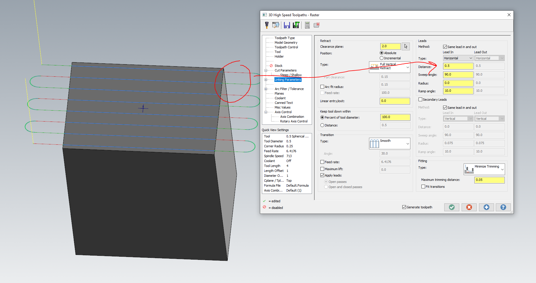
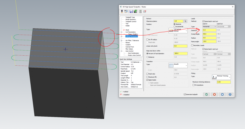
I can understand the confusion, as in 2021 this was explicitly called "Extension", and in 2022 it seemed to disappear. It's simply built into the intelligence of the Leads section of Linking these days. The Distance field is a tangential extension applied before any other part of the lead. Here's an example of what an extension would look like in 2022:
-
Perhaps I'm missing something, but is there a reason you wouldn't just add this extension in the Linking parameters of the raster if you want this extension across the entire path? This is model-aware as well, so it will trim the extension automatically around avoidance geometry.
-
I looked into the file you sent, and this behavior only occurs with the SCREW 1 custom plane, and only while Associativity is checked. You can't copy or select this SCREW 1 plane properly- weird behavior. If I edit the plane and uncheck Associativity, the plane begins functioning normally and you can swap the helix bore ops to using it. I've passed this file on to see how this plane got in this state. If you have any information on how you created/manipulated that plane that you think might be useful, let me know and I'll pass it on as well.
-
I don't see this issue, but perhaps I'm not hitting upon the exact circumstances that are triggering it. Can you post or send me the file?
-
Plane Creation for 5th axis Indexing
Chally72 replied to [email protected]'s topic in Industrial Forum
By dragging out a dynamic plane, briefly throwing it down somewhere on the screen, and then clicking on the arrowhead of an axis, you can also reorient the plane vector along any line or edge you hover over. No need to create a plane from one of the plane creation dropdown choices to get that ability. -
Like I mentioned in that thread- you're specifically asking for that behavior as a user. I don't understand what the behavior change would be- do you want the toolpath to ignore what you are asking?
-
Awesome to hear they got it sorted. Sorry you ran into trouble here!