


Chally72
-
Posts
499 -
Joined
-
Last visited
-
Days Won
32
Content Type
Profiles
Forums
Downloads
Store
eMastercam Wiki
Blogs
Gallery
Events
Everything posted by Chally72
-
Back spotting/Back chamfering centrifugal/hydraulic tools are something we are looking at supporting in a much more natural way in the future.
-
I posted this on the official forum as well, but- great suggestions, and they're logged as follows: R-29984- Add ability to edit multiple segments at once R-29985- Add spreadsheet style navigation to segment grid R-29986- Add math calculations to segment grid
-
Can you tell me which what Version and Update # you're on that this started occurring? Here's what looks to be a very similar thread on this issue on the official Forum: https://forum.mastercam.com/Topic45257.aspx
-
You nailed it, yeah. Unfortunately, the "native orientation" for a solid body used in a stock model is always world Top, so you can never control the "From" plane of the transformation. It works fine if you're using the old-school way of creating stock of just punching in the bounding box numbers, but I almost always work off a solid body these days because I think it's much more powerful down the road. What this means is that if you wanted to do tombstone work and also use a solid model as stock, and your tombstone is way out in space/away from world top, you get this as a workflow:
-
Hi Sendithard, This has to do with the planes checkbox in Stock Model. When you import a body/stl and try to use it as a stock model, it is located at Top (world coordinates) So, before you create your stock model operation, you should manually translate the stl/body to where you want to see it in relation to G54. Then, create the stock model operation and make sure planes are turned off (unchecked) so that you're not applying a transformation to the model. Here's the second video in that Stock Model series that goes over when and how you might use the planes transformation, on both imported stock and in-setup stock:
-
Glad you got some value out of the video! To explain how that part I showed in the video gets around the ghost cut: If you turn on your Minimum Z height in the Steep/Shallow parameters, and it is greater than the height of the stock that you're telling the operation to use, then you won't get the facing cut, and the very first cut will be a full stepdown distance from that Min Z height you entered. When you don't manually enter a Min or Max Z, Optirough just looks at the geometry you selected and sets the Min and Max Z to be the Min and Max extents of the geometry you want to use. Thus, if your stock model sticks above your part still, (IE, Optirough "sees" stock above your min Z) then it creates an initial facing cut to ensure that you have no possible way to inadvertently enter into stock deeper than your tool flutes can handle. Hope this helps!
-
Hey Sendithard, The Titan tutorials do a great job of showing a single process to get a working part file, but they just don't have the time to go into the depth that is offered by the different types of stock models in Mastercam. Optirough will create a "facing" cut on the top of the part if it still sees stock left to clean. This is to ensure it can safely take its first full stepdown cut. There's a lot of options here that may be the cause, but making sure it correctly knows that you faced the part in the previous op, then correctly setting your stepdown and your Min and Max Z depths for the Opti, are key points that will determine whether it makes your ghost cut or not. The Titans tutorial gets around this issue by telling you to make your stock as if you already faced the part. So to follow their flow, you need to lower the face of that stock block that you drew. In your part file, I just used Model Prep Push Pull to drop the top of your stock block on Level 2 by 0.020 to match the top of the part, then regenerated the Optirough, and no more false facing cut! The "proper" way to handle this on your real parts in the future would be to make another Stock Model as Op 3 that represented the part after you took that facing cut, and then your Optirough would be Op 4 and would use the Op 3 stock as its Starting Stock. This is a little overkill for the Titans lesson, so they left it out for the sake of simplicity. Here is a video that might help with explaining the more advanced use cases of those different types of stock:
-
That's due to the simulator taking the best guess at what machine behavior will be. In the machine simulation setup, you can modify that solution bias to better mimic what your machine is doing and get a little closer to a 1:1 simulation.
-
Awesome. Can confirm that R-14452 is still an active item.
-
Hey CNC Asylum- Since we don't have knowledge of the machine kinematics at the toolpath level, all we're doing here is commanding vectors in space. The machine post will decide the side this will end up on (A90 or A-90). An easy way to change this, if your post reacts to values in your machine definition, is to edit the local copy of the machine definition that's in the part file, and artificially restict it to something like A-30 to A90, to force it to always stay on the side you can see it. It's easy enough to edit these values and re-post and see if it gave you what you needed.
-
Hey Steve, this isn't my area and honestly I'm confused by the request. The minimum toolpath radius you rough with determines what's left to clean when you take your finish pass. The path is doing exactly what you ask it to do and I just don't see it as an issue when I use this path. The functionality is identical to if you say, used an Optirough to cut a pocket and then used a Contour to finish the walls. Your corner stock to clean is dependent on what you told the Optirough to use for a minimum radius. To ask for different behavior is to ask that the path ignore the values you're entering in Minimum Toolpath radius. It's also completely valid to have a roughing with a large minimum toolpath radius and then do a finishing pass with a feedrate/rpm override that takes a slower pass with a bigger chunk all at once. I'd recommend emailing your reseller to get an official request number for this so that the Mill product owner can look at it with the team- my opinion on this functionality is just that- an opinion and not the final word- and they might have a different view. If you already have a request number, you can post it or message it to me and I can take a look and see the current status and let you know what's going on with it.
-
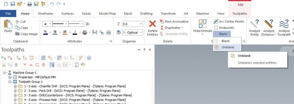
You likely brought in a file or geometry that has a blanked entity. Blanked entities are entities that exist on a level but are "blanked", or hidden, unless you deliberately go and unblank them. There are a number of ways, both automatically and manually, that a blanked entity can be created- such as when you trim a surface, it can save off an original version of that surface as a "blanked" entity so that it's hidden from view but still available if the user needs to get at it. If you are simply window selecting solids/surfaces on the screen and then changing their level, you're not going to be able to fully "empty" a level of all its entities. You can see blanked entities, and unblank them, by using the blank/unblank commands on the Home tab:
-
In the case of two setups in a single machine group, you'd have to simulate them separately and change both the fixturing and the starting stock to reference Setup 2 conditions when simulating Setup 2.
-
What a helpful anonymous Mastercam multiaxis user. Thanks Aaron!
-
The key thing to remember here is that what you're seeing with the blue lines is the path of the center tip of the lollipop tool- not the actual contact point of the flute against the radius. If you were to draw the actual contact lines for each pass on that radius, you would see a perfectly even stepover. To get rid of these 'extraneous' passes, what we need to calculate by is actually cusp height, not stepover- since in areas where the surface radius gets close to the tool radius, we don't need as many passes to get the same surface finish and we mentally see these close together passes as "wasted" motion. This would mean we'd have to calculate a variable stepover along the surface. Now, for this example it seems reasonably feasible to do so (calculate a path by dynamic cusp height rather than stepover,) but when you throw in compound surfaces, changing tool axis control at each point along the path, transitioning between radii on the tool with something like an accelerated finishing cutter, etc- it becomes fiendishly difficult to accomplish correctly. We can do this in a path like equal scallop specifically because we've fixed some of these variables- such as we only have one tool orientation. One old-school way to reduce the pass count would be to offset the surfaces by the radius of your tool, and then generate the path on the offset "centerline" surfaces without tool comp- that way the stepover doesn't contract when projected back to center when it hits the fillet area.
-
Hey Bill, if you've got multiple parts/fixtures you're transforming the stock between, this is what I touch upon in the second half of the second video. If you've got a single part location, then just uncheck that Planes option in every single stock model as it's not necessary. If your situation was the former, this starts to become a complex scenario because your planes are just applying relative transformations, or XYZ and rotational deltas, to move the stock from one area to another. So if you started from a solid body, which is located in World coordinates, but your setup 1 origin was not in the exact same place as World coordinates, it can get difficult to visualize. Here's another (poorer quality) video I made a while back to try to explain this. This is a difficult concept and I wish it was easier/clearer to the user that the entire use of those planes is just to apply relative transformations to the stock position.
-
It's not just acceleration, but stuttering/lag- especially if you were on the limits of what the tool can do. Your specific machine behavior with G2/G3 and G1, and transitioning between them, should guide if you use these settings- not just the reduced line count factor. Some machines will stutter badly when transitioning through arc moves, and this can really hammer the tool with all the stop/go changes rather than staying properly in the cut. The next question- what was your goal with the filtering to begin with? Was it just to reduce program size? Why- to avoid drip feeding? If the program fit on the control, adding in filtering is basically trying to fix a problem that doesn't exist. Was the machine already stuttering with the current code before you added filtering, and this is what you were trying to address? Knowing your goals with these options, and knowing what your machine likes to see (linearized code or arcs, more point density or less) is critical to seeing beneficial results when making changes in these options.
-
Hey Bill, This has to do with the Plane Transform options of Stock Model and it's difficult to explain, so I'm posting two videos below on how this is usually accomplished. Basically, you have two initial approaches that decide how you handle stock models and plane choices. Let's go over these first to better understand how/why that stl location changed. When programming a single part, multiple fixture/multiple vise setup, we have two choices: Have one master model of the part, and "rotate" the fixturing around the part in space to represent Setup 1 and Setup 2. (In this case, a twin vise setup would have one vise at "top" orientation and one vise at "bottom" orientation in space- so if you turned on all levels at once the vises wouldn't actually look like they were side by side like they would be in the machine) The benefit of this method is that all your toolpaths are on the single master model and any changes to your part model in the future need only be made in one place. Have multiple models of the part, and change/transform the location and orientation of each to fit it in fixturing you have modeled. (Such as twin vises sitting side by side) The advantage of this is you physically see the multiple fixture/multiple pocket setup as you would bolt it to the machine table in real life, but now you have multiple copies of the master model geometry and if you did something like change a chamfer width on the part, you'd have to do it in two places. Now, the plane transformation options in Stock Model operations exist specifically for the latter scenario here- where we have to move the part stock in space between pockets on a tombstone or fixtures on a table. That Plane checkbox, in my mind, should remain off at all times unless you run into a specific scenario where you need it on. Otherwise, what you do when you turn that checkbox on for the first stock model operation is "Create" the stock in a specific plane, or coordinate system. And if you ever change that plane, (IE, save the stock out to a STL,) it has to translate that to the world coordinate system. This is why you see it in a different position, but then when you recreate the stock model and reselect the STL and apply the same plane transformation to it, it snaps back to the original location. Here are those videos on the two types of part flow and maintaining stock model associativity. Apologies for the quality of the first video. Let me know if you have questions on what I cover in them. The second video covers scenarios where you'd be moving stock between pockets and even between machine groups and between machine types, such as moving lathe stock to a mill fixture and continuing on with perfect associativity.
-
I do know the color and icon tweaks for 2023 had a lot of thought put into them for things like colorblindness and every possible user color config under the sun. I think in a lot of respects, UX has the most difficult job for new functionality or changes, with all the color config options we allow and legacy configs/personal favorites that all have to be compatible.
-
Hey Shiva, There are a few levers we can pull in multiaxis paths to enact surface finish changes without just adding zeroes to the cut tolerance. Take a look at controls like Damp on the Cut pattern page, and especially all the controls like Points Distribution and Smoothing on the Cut Pattern Subpage, "Advanced Options for Surface Quality". That's where you'll find most of the like for like options. In short, ignoring the arc settings which aren't applicable to linearized multiaxis code, most of the controls you see on the 3 axis paths do exist in one form or another across different areas of (most of) the multiaxis toolpaths, just not organized the same. You've also got tool posture to think about at all stages of the calculation, which is the single biggest contributor to scrubbing, slowdown, micro-gouging/stippling/etc that can affect the end result. Check out this video which walks through methods of improving a multiaxis toolpath for surface finish. Hopefully it gives you some ideas on thinking about how to tweak your specific application for the best motion:
-
Just a note that 2023 has some icon color changes that will alleviate some of these visibility issues.
-
This is now logged as R-29525. Since Mill Flutes Only is checked by default in new files, this is something that went mostly under the radar.
-
Hey all, Just a note that the Mastercam Youtube Channel has been updated with new 2022 Signature Parts videos that can be seen in the Signature Parts playlist even though some videos are still currently unlisted. Here are a few of the new ones. More still to come in the next few months, as well!
-
This is a pleasing pattern to the eye, but is not maintaining a constant cutter engagement throughout the path.
-

Moving/Rotating Solid Faces - Gnomon Issue
Chally72 replied to SuperHoneyBadger's topic in Industrial Forum
If you're not aware, the Ctrl key is a shortcut that toggles between the Geometry Move and Gnomon Move states of Dynamic Transform, so you don't have to find and hit that little icon!- 4 replies
-
- 2
-

-

-
- move
- solid face
- (and 2 more)
