Chally72
-
Posts
499 -
Joined
-
Last visited
-
Days Won
32
Content Type
Profiles
Forums
Downloads
Store
eMastercam Wiki
Blogs
Gallery
Events
Everything posted by Chally72
-
Mesh entities do come in with a normal, even if you can't display it in earlier Mastercam versions. Even if you can't flip the normal directions, you can still simply change your tool axis control method or tool plane to force the tool to come from the opposite side, just as you can with surfaces:
-
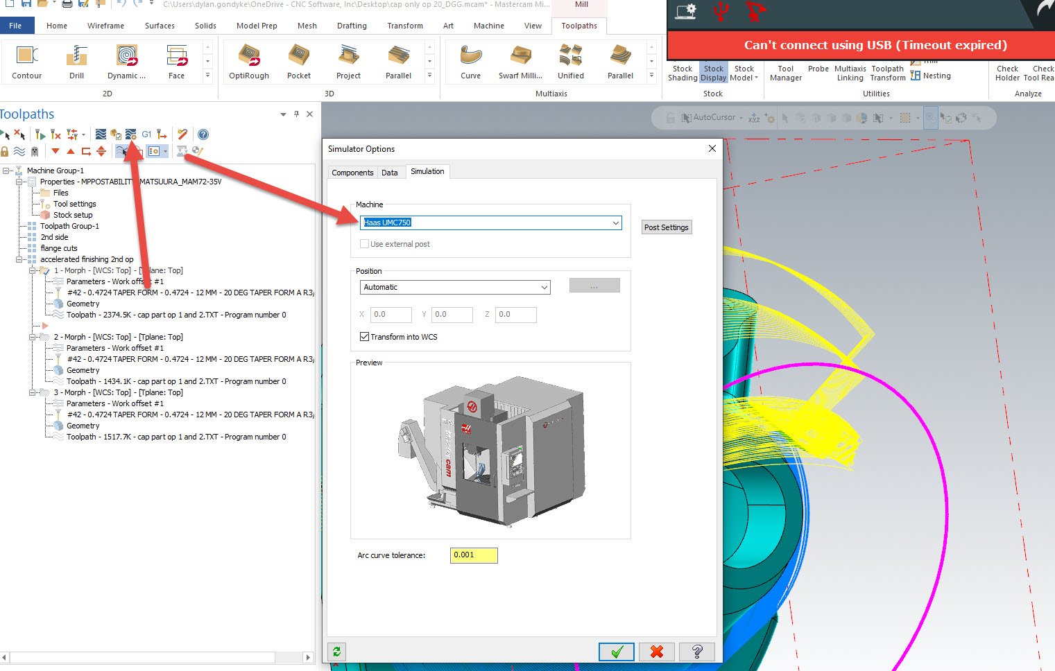
There are many changes in 2022 that have reduced these occurrences, and there will be more in 2023. One of the big causes is if you're using a file that had a specific machine in the Simulator options, and now you open and try to verify an operation on a PC that doesn't have that machine. See below- If I saved this and sent it to someone without a UMC in the MachSim folder, they might have trouble launching Verify. Even though the machine model isn't used for Verify, it still tries to load up all the settings in these panes and if the machine doesn't exist, there can be issues with the load that give you the Verify unknown error. Even if you don't think this is your cause, when you run into the Verify error, try going into the options and toggling that machine selection to something else and then back, then retry the Verify launch. Hope this helps.

-
If you're willing to shoot me a file link via PM, I can take a look at the mirroring and attempt to figure out what's going on. One thing that is a challenge (depending on your mirror choices) when mirroring paths is determining how to solve all the circular dependency issues created if you're referencing stock within your operations. So what Metallic has probably done, and what you need to do in these cases, is to create a separate mirror for every string of operations that exists between stock models in the tree, and then sometimes create separate stock or rough operations for critical stock-aware parts of the program before continuing on. This issue arises because we're programmatically mirroring an operation which references the original, non-mirrored stock, and now we have a dilemma about if the original reference was the intent or not for the mirror, etc etc. Mirroring tools don't always allow the power we need to explore all scenarios that may exist, especially on a complex part like Metallic has posted, so it often takes a bit of time and workflow adjustment to get it right in a case like that.
-
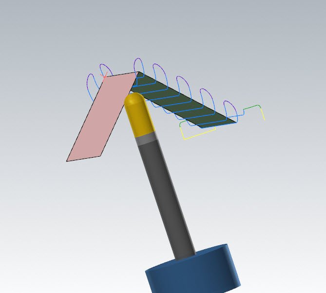
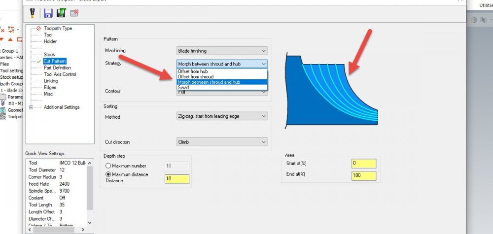
This is even if using Morph Between Shroud and Hub? See picture below. This opens up a new surface selection on the Part Definition page for a Shroud surface- IE, you could have a revolved "Lampshade" that represents the outer extent of your blades, and the blade finishing would blend between this and the blade root in the exact manner that a Morph would with the same blade extents selected.
-
If you're adding via the 1 or 2 distances method, then you aren't actually asking that it respect a 45 to either edge- you're asking for specific conditions for the bestfit of the chamfer between the two edges you're applying the chamfer to.
-
Correct- the intersection of the chamfer at the tangent of the arc is affecting the outcome. If you're adding an equal Width+height chamfer to any corner that isn't a true 90 degrees, it has to pick a median. Here you know the answer you want- you'd like the chamfer to remain 45 to the bottom edge- but to the software, 45 to the tangent of the arc rather than your bottom edge would be just as valid- so it's a case where you need a very specific relationship for the chamfer angle and should draw it out.
-
In Mastercam 2022, you can view and flip the surface normal direction of mesh entities, so that would make this a simple fix. In 2021, I'm not actually sure if there's any way to even view mesh normals. There are a few different ways we could still work around this and force the machining from the backside. If you can upload a file, I could provide an example.
-
The splitter is a common feature and shouldn't effect the outcome. Without seeing the file and poking around, Gcode has provided a good start point. If you can, post the file so that we can take a look. Here's the file on the tech exchange: https://community.mastercam.com/TechExchange/Parts/1476#partTitle
-

Making the Cut- Mastercam Toolpath Deep Dives
Chally72 replied to Chally72's topic in Industrial Forum
Moving the help to a web-based format is allowing us to greatly expand upon what we offer for content. I believe that video and animation is one of the end goals of future help. We definitely want to leverage these Signature Parts series videos as help content anywhere we can, as I'm a hands-on learner and I think having help show you not just the functionality, but the real-world application, of a feature is critical to getting the most out of it. Have you checked out the help page on some newer features? The team has done a fantastic job of explaining some of these things with graphics and step-by-steps. Check out the linking help on 3D HST paths, for example. I didn't even know what the Maximum Lift field was for until reading down through the help. Paste that link in your browser to open it up locally if you've got the default install location: file:///C:/Program%20Files/Mastercam%202022/Mastercam/help/en/Content/Toolpaths/Common/Linking_Parameters_3D.htm?cshid=11925 -
Making the Cut- Mastercam Toolpath Deep Dives
Chally72 replied to Chally72's topic in Industrial Forum
Hey JrScott, I actually don't often go after arc filter tolerances very much for the machines I work with. For arc filter and smoothing adjustments, the goal would be very similar to what we went after in the 5 axis path- What do we need to do to tailor the motion so that our specific machine likes it? The biggest thing that I see people do is to leave the roughing tolerance at the default 0.001" even when leaving, say, 0.020" stock. Take advantage of a bit of the stock band there to loosen up the roughing path- and same with applying the arc filtering. The end goal would be roughing (or finishing) motion that the machine can keep up with, so there are no slowdowns either because of code density choking the control, or acceleration rates that the axes can't handle. Speed changes = uneven chip load = tools die sooner. In that respect too, some controls (fanuc) really like the fixed segment length field here to evenly space the points. Find a settings combo that your machine is happy with, and apply that moving forward. Even if you can't visually pick out major changes, the final cycle time on a 5 minute roughing program is going to be revealing as to what your machine thinks of your tweaked points. -
Direction on solid hole for drilling changing sides
Chally72 replied to Programinator's topic in Industrial Forum
I haven't seen this one before. Can you send a file in for QC to take a look at? -
Making the Cut- Mastercam Toolpath Deep Dives
Chally72 replied to Chally72's topic in Industrial Forum
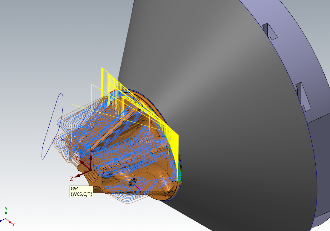
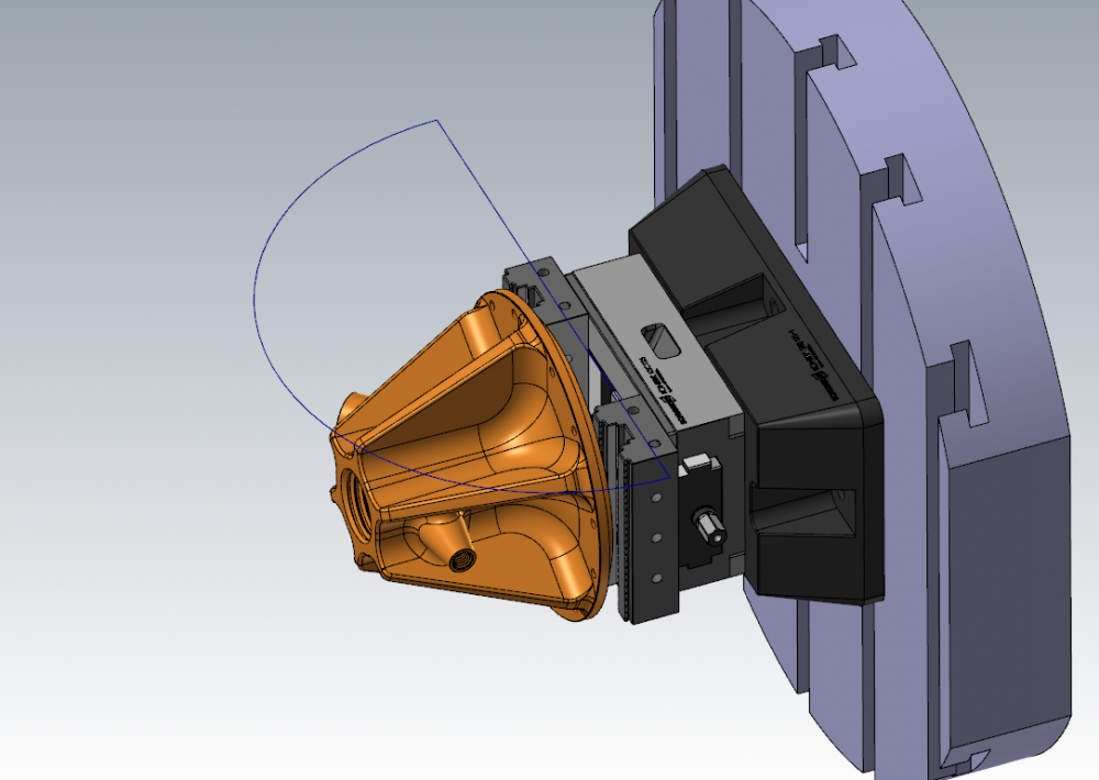
There are a few different ways we could trim the motion here and keeping the tool from reaching around the backside. (Even while using starting stock, etc, we still want to use one of these methods!) The first is to add the fixturing in as avoidance geometry. In the picture below, that would be the vise/etc. There are a few downsides to this, however- -The stock must be perfectly positioned on the vise or you risk collisions OR have to unnecessarily puff the avoidance distances. -Fixture modeling like this is really nice to look at visually, but extremely expensive computationally- especially if we're adding stock to leave and each individual surface must be offset before toolpath calculation can begin. Another way to do this is to make a simplified solid that gets you avoidance around the fixturing without the complexity of 3000 fixture surfaces as your selection. Below, this cone was a nice way to keep the tool away from bad areas without spending a lot of time on avoidance: Since Optirough with rest stock needs to have a containment boundary no matter what, though, the method I most often use for this kind of single-setup 3+2 work is to just draw a big semicircle like below and set it as my containment, where the wireframe line represents my hard boundary that I don't want the tool to go behind. This gives the path plenty of air region around the part and stock only in the direction I want it to- the table+ direction- and eliminates any wasteful/inefficient cuts where it would try to dive around the underside of the part by the vise to nibble away at edges, where I'm likely going to clean up the material anyway in the flip op for Setup 2. Around a part like this, you might see that semicircle Transform-copied 6 times to give me boundaries for my 6 pockets and my 6 Optirests. If you'd like to go over any more specific examples as you work through a roughing strategy, feel free to post the part or send it over and we can talk through options. For those that don't know, there's another Making the Cut video that goes over 3+2 rest roughing on a similar part, utilizing stock models and a few other key tricks to make sure we're as efficient as possible. It doesn't go much into Metallic's specific question, since on that part there are clear interior pockets where we can simply use a Silhouette boundary, and don't run into the quandary of open air pocket ends and how to manage where the tool should or should not be at around the perimeter of the part.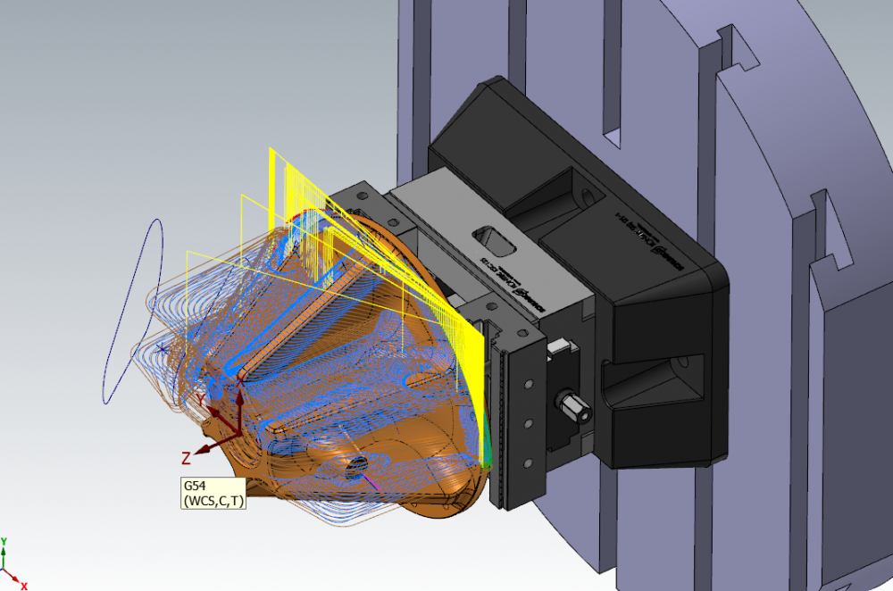

-
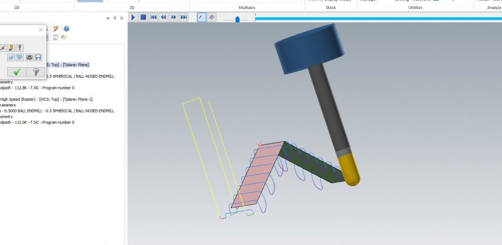
Here's a fun multiaxis video that puts a toe in the deeper end of the pool and gives some insight into when to go after parameters like Max Angle Increment, Cut Tolerance, and Maximum Distance, as well as using the oft-ignored and slightly opaque "Smoothing" subpage of Collision Control. There are a few Making the Cut videos on our Youtube page already and more to come in the future, where we focus on some of the theory behind a specific toolpath or process. Hopefully this is valuable for some!
-
No problem, and apologies I don't have a better answer
-
If you're using 2022, this is all built into the interface now. I'm unaware of any way to un-link relative planes in older versions of the software. That was one of the reasons the interface changes were put in and there's icons and options all over the plane creation and plane manager now- It was previously unknown to the user what planes were linked and to which.
-
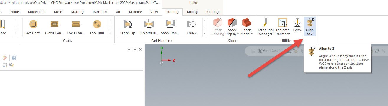
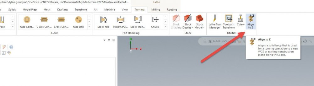
There is a flip button in the Align To Z panel where you can flip the Z direction. When you click on a cylinder or surface, it'll place the gnomon at one axial end of the solid you clicked. You can always click on the Z arrow of the gnomon it places and simply drag it/snap it to a new Z origin if you didn't want your origin to land there. To make my Setup 1 and (Flipped) setup 2, I just use the Align to Z command twice to create my two planes I will use, and for the second I'll make sure my Z direction is flipped and dragged to the opposite extent of the part. I almost never move the model, as it prevents you from, say, importing a new rev model quickly and cleanly. I'm always creating planes in different orientations as described above with Align to Z.
-
A very simple way that I use to make a Lathe plane without having to think too much is the Align to Z command you get in the lathe ribbon: You can either transform the part to an existing plane, or let it create a new plane and keep the model in the same orientation as it was imported. I always use the latter. This takes most all of the pain out of setting up lathe planes that newer users can experience. Even I get confused by lathe planes still.
-
I would actually also suggest looking at Edit UV, where you can select multiple surfaces and then auto-align their UV's based on a seed surface. Overflow has more control over pushing a specific UV pattern to the final shape, but if you just need to clock the UV's the same, Edit UV is the fastest way to do so. In short- Reflow UV- a good way to specifically reflow UV's on a single surface Edit UV- a good way to change or mass-align UV's on groups of surfaces simultaneously Overflow UV- a good way to create new patch surfaces with a new trimmed boundary, encompassing one or more existing surfaces, with a very specific projected UV grid. See this video for examples of the former two:
-
This is purely a calculation switch, so you're not actually running at ball center in posted code- you're just changing the toolpath creation technique!
-
A very good point that often goes overlooked. Also, if you're going to end up with a Spiral cut pattern choice on a multiaxis path, leave that set to one way or zigzag, and change it back to spiral along with the final stepover as the last changes you make to the path. Spiral is another choice that can drastically increase calculation time.
-
You get used to modern convenience quickly. 5 years ago I was soldering an RS232 cable to drip feed to my first CNC machine- a used 1980s Okuma. A few weeks ago I had to use a Compact Flash card on a newer machine and it felt like the biggest bother of 2021 so far.
-
James, what is the error upon launch?
-
Remember that even with a lot of work here, you still can't match your real life scenario 1:1. Acceleration rates for each axis, even if your machine builder provided them, are in an unloaded state. Put 300lbs of fixturing on top of everything, and maybe suddenly the X is much slower to accelerate than the Y, and now you have dogleg motion that is entirely different than your dialed in Machine definition motion. This means something that just barely clears in Verify now clips your part in real life. For this reason, it's safest to convert rapids to feeds if you're going to be moving around between part features or stock without lifting the Z.
-
Right now, the only thing that approximates subgroup versatility is properly set up viewsheet groups.
-
It is important to point out the difference between MBD data on an actual solid model saved in .PRT format, and drawings/blueprints done in UG/NX and saved in .PRT format. The latter is, to my understanding, only readable by an actual seat of NX. By QA department's software, what software package do you mean? What did the file contain?