


Werktuigbouwer
-
Posts
56 -
Joined
-
Last visited
-
Days Won
2
Content Type
Profiles
Forums
Downloads
Store
eMastercam Wiki
Blogs
Gallery
Events
Everything posted by Werktuigbouwer
-
I am working on a simular project to use a pyramid. Therefore I recreated the Excel file (to make it eventually to a macro), use at you're own risk. Be aware it is depended on the machine. kinematic point.xlsx
-
View only version of standalone tool manager
Werktuigbouwer replied to ThisGuy's topic in Industrial Forum
Best bet is to use a file synchronization program (in the past i used SyncToy). You're PC will be the master and create at a fixed time of the day a backup on the network. At the operators PC, at startup a clean version of the backup will be placed in a local folder, from which the standalone tool manager can be opened. If they alter the database, the next day the database is then restored. The operator can never alter you're own database. Only downside is, that the database is at most a day old (for new programs this can be a problem). -
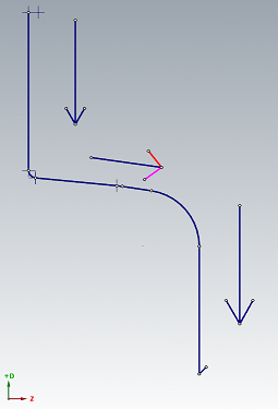
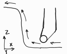
If I draw you're code in Mastercam (in the standard lathe plane D+ Z+) the G2 and G3 looks correct. You're sketch looks wrong (axis reversed). Y-axis is pointing into the drawing based on right hand rule. Then we have to look from the back side and then the rotations are also correct.
-
MPMASTER Based Post - No Rotary Output
Werktuigbouwer replied to SuperHoneyBadger's topic in Post Processor Development Forum
The problem is placed in the following part pfcout #force C axis output if index = zero & rot_on_x, [ if use_rotmcode & (fmtrnd(cabs) <> fmtrnd(prv_cabs) | sof), *sindx_mc if absinc$ = zero,[if machinex >9, *cabs], !cinc, !cout_i else,[if machine>9, *cout_i], !cinc, !cabs ] the output of the A axis is only when machinex >9 or machine>9 while in the post these are defined as: machine : 7 machinex : 7 Changing pfcout to: pfcout #force C axis output if index = zero & rot_on_x, [ if use_rotmcode & (fmtrnd(cabs) <> fmtrnd(prv_cabs) | sof), *sindx_mc if absinc$ = zero,[if machinex >6, *cabs], !cinc, !cout_i else,[if machine>6, *cout_i], !cinc, !cabs ] will give you the output you desire -
Post Processor comments to header
Werktuigbouwer replied to CMDesign's topic in Post Processor Development Forum
Try the following adjustments sav_commentfilter : 0 # variable to save the commentfilter pheader$ #Call before start of file if wcs_mode <> two, # Yes, read 'mi1' to set 'wcs_mode' [ if mi1$ = zero | mi1$ = one, # Get Work Coordinate System mode setting wcs_mode = mi1$ # 'G92' output modes w/ 'G28' retracts else, wcs_mode = two # 'E' fixture offset mode ] else, wcs_mode = two # 'E' fixture offset mode "%", e$ n$, *progno$, "(", sprogname$,")", e$ sav_spc = spaces$ spaces$ = 0 #*progno$, sopen_prn, sprogname$, sclose_prn, e$ n$, sopen_prn, sspace, "CREATED ON - ", day$, "-", month$, "-", year$, " AT - ", ptime, sspace, sclose_prn, e$ #n$, sopen_prn, sspace, "PROGRAM NAME - ", sprogname$, sclose_prn, e$ #n$, sopen_prn, sspace, "DATE=DD-MM-YY - ", date$, " TIME=HH:MM - ", time$, sclose_prn, e$ #Date and time output Ex. 12-02-05 15:52 #n$, sopen_prn, sspace, "DATE - ", month$, "-", day$, "-", year$, sclose_prn, e$ #Date output as month,day,year - Ex. 02-12-05 #n$, sopen_prn, sspace, "DATE - ", *smonth, " ", day$, " ", *year2, sclose_prn, e$ #Date output as month,day,year - Ex. Feb. 12 2005 #n$, sopen_prn, sspace, "TIME - ", time$, sclose_prn, e$ #24 hour time output - Ex. 15:52 #n$, sopen_prn, sspace, "TIME - ", ptime sclose_prn, e$ #12 hour time output 3:52 PM spathnc$ = ucase(spathnc$) smcname$ = ucase(smcname$) stck_matl$ = ucase(stck_matl$) snamenc$ = ucase(snamenc$) #********************************** Added lines***************** sav_commentfilter = comm_filter$ # save comm_filter comm_filter$ =1110011111 # set comment filter comment$ # add comments comm_filter$ = sav_commentfilter # restore comment filter #********************************** End of change ************** #n$, sopen_prn, sspace, "MCX FILE - ", *smcpath$, *smcname$, *smcext$, sspace, sclose_prn, e$ #n$, sopen_prn, sspace, "NC FILE - ", *spathnc$, *snamenc$, *sextnc$,sspace, sclose_prn, e$ n$, sopen_prn, sspace, "MATERIAL - ", *stck_matl$, sspace, sclose_prn, e$ spaces$ = sav_spc pcomment2 #Output Comment from manual entry scomm$ = ucase (scomm$) if gcode$ = 1005, n$, no_spc$, sopen_prn, scomm$, sclose_prn, e$ #Manual entry - as comment if gcode$ = 1006, n$, scomm$, e$ #Manual entry - as code if gcode$ = 1007, sopen_prn, scomm$, sclose_prn #Manual entry - as comment with move NO e$ if gcode$ = 1026, scomm$ #Manual entry - as code with move NO e$ if gcode$ = 1053, [ n$, *e$ n$, no_spc$, sopen_prn, scomm$, sclose_prn, e$ #Group name n$, *e$ ] if gcode$ = 1008, n$, no_spc$, sopen_prn, scomm$, sclose_prn, e$ #Operation comment #if gcode$ = 1051, n$, no_spc$, sopen_prn, scomm$, sclose_prn, e$ #Machine name #if gcode$ = 1052, n$, no_spc$, sopen_prn, scomm$, sclose_prn, e$ #Group comment if gcode$ = 1054, n$, no_spc$, sopen_prn, scomm$, sclose_prn, e$ #File Descriptor Greetz Jan- 6 replies
-
- 2
-

-
- post
- postprocessor
- (and 1 more)
-
Examples of using Excel within your Manufacturing experiences
Werktuigbouwer replied to #Rekd™'s topic in Industrial Forum
In the past i made an Excel file to determine the optimal tool order for a turret lathe and a "near" optimal tool order for a fixed tool magazine mill. This uses Excel for the program input and machine input. Then with VBA it calculated the results. After calculation the results were showed in Excel. I say near optimal tool order, because it is imposible to calculate every posible solution in an acceptabele time. On average i saved a second a minute. Which is a lot in mass production -
0.029" external grooving tool
Werktuigbouwer replied to So not a Guru's topic in Machining, Tools, Cutting & Probing
other option: PHorn: Insert: https://eshop.phorn.de/S64T007000EG55 0.77 mm width 0.0303..." Holder: https://eshop.phorn.de/LH64T252510 left hand or: https://eshop.phorn.de/RH64T252510 right hand -
I did not projected the line. I created a line from the quadrant, and used tangent arc. The mesurement of the two radi i got from the push pull function in the model preb tab. For me this was the easiest method.
-
On the wireframe tab there is a function creatie spline from curve, it asks to select the curves. You can keep or delete the original curves. For level 14 i used swept surfaces, note that i created the wireframe geometry from your solid, but extended it to outsider mine revolved surface.
-
Make sure it is a spline to revolve or you will get multiple surfaces.
-
Is this what you were looking to accomplish? HELP..mcam First i made a cross section wireframe of the solid model, see level 11. Here i added a radius entrance, not a straight line. Then i converted the curves too an spline. See level 12. Next i created a revolved surface with this spline. See level 13 After this i needed to create surfaces to trim the revolved surface to stay within the vein. See level 14. Here i used to chains to create a swept surface. In level 15 i used the revolved surface as trim set 1 en the surfaces in level 14 as trim set 2, to trim the revolved surface, by using de function trim to surface Greetz Jan.

-
Living in Europe, this is all standard for me. M10 has a standard pitch of 1.5 mm, M6 has a pitch of 1 mm and M12 has a pitch of 1.75 mm. If a customer wants a fine pitch thread (standard is coarse) then he or she should define it as M10x1 The x1 defines the pich. With you're call out M10-6h, the 6h defines the thread class. (6h is the standard thread class) The link below, gives some information on the metric threads. https://media.bossard.com/es-en/-/media/bossard-group/website/documents/technical-resources/en/f_079_en.pdf Greetz, Jan
-
How to Change Cutter Comp. position in Lathe
Werktuigbouwer replied to @Mastercam's topic in Post Processor Development Forum
Hello, I had the same question, but did not had the time yet (until yesterday and today). I came up with the following changes to the standerd post: # -------------------------------------------------------------------------- # Custom variables # -------------------------------------------------------------------------- op1_G41 : 0 cc_pos_pre : -1 # add variable JHM 2021-02-12 # # add variable to lsof$ lsof$ #Start of file for non-zero tool number, lathe sav_cc_1013 = cc_1013$ op1_G41 = 0 # 2021-02-12 initialize variable for first op G41 ltlchg$ # Added logic to ltlch$ ltlchg$ #Toolchange, lathe toolchng = one gcode$ = zero copy_x = vequ(x$) pcc_capture #Capture LCC ends, stop output RLCC c_rcc_setup$ #Setup LCC on first 60000 plcc_lead_begin #Save original in sav_xa and shift copy_x for LCC comp. pcom_moveb #Get machine position, set inc. from c1_xh c_mmlt$ #Position multi-tool sub, sets inc. current if G54... ptoolcomment comment$ if home_type < two, #Toolchange G50/home/reference position [ sav_xh = vequ(copy_x) sav_absinc = absinc$ absinc$ = zero pmap_home #Get home position, xabs ps_inc_calc #Set start position, not incremental #Toolchange home position if home_type = one, pbld, n$, *sgcode, pfxout, pfyout, pfzout, e$ else, [ #Toolchange g50 position pbld, n$, *sg28ref, "U0.", [if y_axis_mch, "V0."], "W0.", e$ toolno = t$ * 100 + zero if home_type = m_one, pbld, n$, *sgcode, *toolno, e$ else, pbld, n$, *sg50, pfxout, pfyout, pfzout, e$ ] pe_inc_calc #Update previous absinc$ = sav_absinc copy_x = vequ(sav_xh) ] toolno = t$ * 100 + tloffno$ pbld, n$, *sgcode, *toolno, e$ pbld, n$, pfsgplane, e$ pcaxis_off_l #Postblock for lathe transition pcom_moveb #Reset machine position, set inc. from last position pcan pspindle if opcode$ <> 106 | (opcode$ = 106 & suppress_point_spindle = no$), #Do not enable spindle for point toolpath [ if css_actv$, [ if css_start_rpm, prpm #Direct RPM startup for programmed CSS else, pcssg50, pcss #NO RPM start - just output the CSS ] else, prpm #Direct RPM was programmed ] sav_absinc = absinc$ if home_type > one, absinc$ = zero # ************************************* New location of psccomp ********************************************************* JHM 2021-02-12 for location of G41 pcan1, pbld, n$, #psccomp, #commented psccomp out to get correct location G41 *sgcode, pwcs, pfxout, pyout, pfzout, pscool, strcantext, e$ # ************************************* Changed location of rpm start ********************************************************* JHM 2021-02-12 for location of G41 if (opcode$ <> 106 | (opcode$ = 106 & suppress_point_spindle = no$)) & css_start_rpm, #Do not enable spindle for point toolpath pcssg50, pcss #CSS output AFTER a G97S???? RPM spindle startup # ************************************* New location of psccomp ********************************************************* JHM 2021-02-12 for location of G41 pbld, psccomp if op1_G41=0, cc_pos_pre = cc_pos$ # Set previous variable for psccomp op1_G41 = 1 plcc_lead_end #Use sav_xa to position with comp. LCC pcom_movea #Update previous, pcan2 ps_inc_calc #Reset current absinc$ = sav_absinc # ************************************* Changed location of rpm start ********************************************************* JHM 2021-02-12 for location of G41 #if (opcode$ <> 106 | (opcode$ = 106 & suppress_point_spindle = no$)) & css_start_rpm, #Do not enable spindle for point toolpath # pcssg50, pcss #CSS output AFTER a G97S???? RPM spindle startup c_msng$ #Position single-tool sub, sets inc. current if G54... toolchng = zero !op_id$, !lturret$, !tool_op$, prv_millcc = zero prev_spindle = spindle_no$ #Save spindle used in this operation #end ltlchg$ # Edit prapidout to comment out psccomp in G0 movements prapidout #Output to NC, linear movement - rapid if lathecc = zero, [ if millcc_flag & (abs(cuttype) = four | abs(cuttype) = two) & cutpos2$ = zero, #Polar interpolation is active & Y-axis subs or Right face or Left face & before start point of operation geometry [ if abs(cuttype) = four, #Y-axis substitution, output C first on separate line [ pcan1, pbld, n$, pexct, psgcode, pcout, e$ pbld, n$, pexct, pxout, pyout, pzout, pscool, strcantext, e$ ] else, #Right or Left face cut, output Z last on separate line [ pcan1, pbld, n$, pexct, psgcode, pxout, pyout, pcout, pscool, strcantext, e$ pbld, n$, pexct, psgcode, pzout, e$ ] ] else, [ pcan1, pbld, n$, psgplane, pexct, psgcode, #psccomp, # commented psccomp out for correct location output of G41 pwcs, pxout, pyout, pzout, pcout, pscool, strcantext, e$ ] ] else, #Lathe canned turning cycle [ pcan1, pbld, n$, pexct, psgcode, #psccomp, # commented psccomp out for correct location output of G41 pxout, pyout, pzout, pcout, pscool, strcantext, e$ ] if force_feed, result = force(feed) # Force output of feed next time it's called for output if rpd_typ$ = 7, ptool_insp #Tool inspection point #end prapidout # psccomp, added logic to forse G41/G42/G40 output to plane$=2 and prevent double output psccomp #Output the cutter compensation based on the current plane if compok | lcc_compok >= two, [ if plane$ = zero, sccomp if plane$ = one, sccomp1 if plane$ = two, #added logic, instead of sccomp2 [ if cc_pos_pre <> cc_pos$, [ *sccomp2 cc_pos_pre = cc_pos$ ] ] ] # end psccomp which gives as a result: G0 T1212 G18 G97 S2136 M03 G0 G54 X43.951 Z5.3 M8 G50 S3600 G96 S295 G42 G99 G1 Z3.3 F.2 Z-59.864 X46.447 G18 G3 X46.847 Z-60.064 K-.2 G1 Z-97.155 G40 X49.676 Z-95.741 G0 Z5.3 X41.055 G1 G42 Z3.3 F.2 Z-59.864 X43.951 G40 X46.78 Z-58.45 G0 Z5.3 X38.159 G1 G42 Z3.3 F.2 Z0. Z-59.864 X41.055 G40 X43.884 Z-58.45 G0 X46.247 G28 U0. V0. W0. M05 T1200 I have not tested it yet, so test carefully Greetz, Jan -
With this you know where the problem is. I would add a variable to the system: op_num_prev : 0 #Variable to store the previous op_num for ptoolcommend Next we have to edit the last else statement: ptooltable$ if tool_info > 1, # tool_info is initalized to 3 which puts Tooltable in header - with tool comments at T/C [ result = fprm(101, 0, 0) # get the data from parameter lookup pgettoolinfo s_t_pre_tt = s_t_pre$, s_d_pre_tt = s_d_pre$, # Copy prefix string for Tool number and cutter comp number s_h_pre_tt = s_h_pre$ # Copy prefix string for Tool length offset # Output tooltable line if tt_state$ = 1 | tt_tool$ <> tool_prev, [ *e$ n$ = tt_tool$ * 100 *tt_tool$, sdelimiter, *n$, sdelimiter,*supmf_id, sdelimiter, pstrtool, sdelimiter, *tt_tlngno$, e$ if tt_drlcycle$ = -1 & comp_type > 0 & comp_type < 4, [ sopcomment, sdelimiter, *tt_offset$, sdelimiter, *scomp_type, e$ ] else, [ sopcomment, e$ ] ] else, [ if op_num_prev <> op_num, # Add this if statement to check to previous operation number [ sopcomment, e$ ] ] op_num_prev = op_num #update op_num_prev ] Also note that every time the added variable is updated in the second to last line. The first if statement after # output tooltable line: if tt_state$ =1 | tt_tool$ <> tool_prev, checks for first tool or if tool is unequal for previous tool. Therefore op_num_prev is not used at before updating it. The added if statement check is the op_num_prev is unequal to current op_num. This should eliminate the extra sopcomments from a toolpath and adding it when there is a new toolpath. Greetz, Jan
-
Try this: ptooltable$ if tool_info > 1, # tool_info is initalized to 3 which puts Tooltable in header - with tool comments at T/C [ result = fprm(101, 0, 0) # get the data from parameter lookup pgettoolinfo s_t_pre_tt = s_t_pre$, s_d_pre_tt = s_d_pre$, # Copy prefix string for Tool number and cutter comp number s_h_pre_tt = s_h_pre$ # Copy prefix string for Tool length offset # Output tooltable line if tt_state$ = 1 | tt_tool$ <> tool_prev, [ *e$ n$ = tt_tool$ * 100 *tt_tool$, sdelimiter, *n$, sdelimiter,*supmf_id, sdelimiter, pstrtool, sdelimiter, *tt_tlngno$, e$ if tt_drlcycle$ = -1 & comp_type > 0 & comp_type < 4, [ sopcomment, sdelimiter, *tt_offset$, sdelimiter, *scomp_type, e$ ] else, [ sopcomment, e$ ] ] else, [ # sopcomment, e$ -------> comment this line out ] ] Greetz, Jan
-
Posting subrograms with .nc or .sub extension
Werktuigbouwer replied to balnh's topic in Post Processor Development Forum
Try the following: Look at the sextaux$ and sextsub$ line pheader$ result = setncstr(two, spathnc$ + snamenc$ + sextnc$) psub_st_s$ result = fclose(spathaux$ + snameaux$ + sextaux$) snameaux$ = drs_str(two, sub_prg_no$) sextaux$ = ".nc" result = setncstr(two, spathaux$ + snameaux$ + sextaux$) psub_st_m$ result = fclose(spathsub$ + snamesub$ + sextsub$) snamesub$ = drs_str(two, main_prg_no$) sextsub$ = ".nc" result = setncstr(two, spathsub$ + snamesub$ + sextsub$) -
This worked for me. Are u using the correct variable? ptooltable #Tooltable output !spaces$, spaces$ = 0 result = newfs(6, t$) sopen_prn, *t$, sdelimiter, sdelimiter, pstrtool, sdelimiter, *tlngno$, [if comp_type > 0 & comp_type < 4, sdelimiter, *tloffno$, sdelimiter, *scomp_type, sdelimiter, *tldia$], [if xy_stock <> 0 | z_stock <> 0, sdelimiter, *xy_stock, sdelimiter, *z_stock], sclose_prn, e$ xy_stock = 0, z_stock = 0 #Reset stock to leave values #Reset stock to leave values result = newfs(4, t$) spaces$ = prv_spaces$ I used newfs to change the output. Result: (T001||VLAKFREES Ø50/Ø57.8 TEAGUTEC |H1) (T002||10 FLAT ENDMILL |H2|XY STOCK TO LEAVE - 1.|Z STOCK TO LEAVE - 0.) (T057||12 FLAT ENDMILL |H57)
-
From memory: go the cofiguration, tab simulation and uncheck OR check go to home position. Then restart mastercam. Tomorrow i will update a screenshot.
-
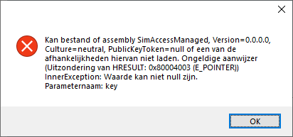
Same problem here, but starting up in compatibility mode gives the following error:
-
2-3 tpi turning
Werktuigbouwer replied to Eric@HorsepowerInc.'s topic in Machining, Tools, Cutting & Probing
I would try Vardex tools ( http://www.vargus.com ), item below is for a partial profile of 60°.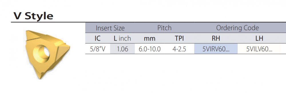
-
I have a MX850 with only the orbital function (synchro tip was not available back then). We use this function to shape vacuum surfaces (round surfaces, but also squares). These surfaces has to have a circular roughness. When we were looking for a new machine a couple of years ago, the salesman said that you could also combine synchro tip with orbital shaping to combine the speeds. Orbital shaping can be done in every plane. But synchro tip has to be centered on the C-axis.
-
Other option: ttblend$ is a variable which indicates last tool call. #prestage tool pbld, n$, "G43", *tlngno$, pfzout, scoolant, if ttblend$, "T0", e$ else, *next_tool$, e$
-
lathe post x5 m6 on tool line
Werktuigbouwer replied to offrey414's topic in Post Processor Development Forum
You probably use as Work coordinate system the option Home position (mi1 = 1) Try changing the post to the following: if home_type < two, #Toolchange G50/home/reference position [ sav_xh = vequ(copy_x) sav_absinc = absinc$ absinc$ = zero pmap_home #Get home position, xabs ps_inc_calc #Set start position, not incremental #Toolchange home position if home_type = one, pbld, n$, *sgcode, pfxout, pfyout, pfzout, e$ else, [ #Toolchange g50 position pbld, n$, *sg28ref, "U0.", [if y_axis_mch, "V0."], "W0.", e$ toolno = t$ * 100 + zero if home_type = m_one, pbld, n$, *sgcode, *toolno, e$ else, pbld, n$, *sg50, pfxout, pfyout, pfzout, e$ ] pe_inc_calc #Update previous absinc$ = sav_absinc copy_x = vequ(sav_xh) ] toolno = t$ * 100 + tloffno$ pbld, n$, *sgcode, *toolno, "M6", e$ pbld, n$, pfsgplane, e$ -
Kitamura cutter comp issue
Werktuigbouwer replied to Noise's topic in Post Processor Development Forum
Another option could be to solve this on the machine side. In the toolchange macro you could set for example: #800 = #4120 (H-offset) #801 = #4120+50(D-offset) (OR +0) Than you have to change the post to call for H#800 and D#801 One program for all machines, down side is that you can not use multiple tooloffsets. I have done this for our Matsuura. -
Active report output a pop up message
Werktuigbouwer replied to PcRobotic's topic in Post Processor Development Forum
I believe you have not copied it correcly, try MessageBox.Show("message")


