


Aaron Eberhard
-
Posts
1,406 -
Joined
-
Last visited
-
Days Won
103
Content Type
Profiles
Forums
Downloads
Store
eMastercam Wiki
Blogs
Gallery
Events
Everything posted by Aaron Eberhard
-
That's actually a tough problem, as all of the toolpaths will want to stitch each slice together so that it goes the entire way around the block (in the case of horizontal) or over it (in the case of vertical), which wouldn't be very "facing-like." Your best bet might be to make the facing ops and then just use Multiaxis Linking to stitch them together safely.
-
You're welcome, sir
-
The Hole Table c-hook was made into a drafting function in 2020 (which works really nicely!), but it never sorted to levels or anything, it was purely CAD functionality. I believe you're looking for the "SortCircles" chook which is still there in 2020. I believe SortCircles works on everything visible, so I think you'd have to hide what you don't want to be sorted, but I haven't used it a lot so I may be wrong there. I did test it again and there's no selection..
-

Change cut direction in multi axis along curve
Aaron Eberhard replied to Leon82's topic in Industrial Forum
No, Cuts Along Curve is designed to be perpendicular to a chosen curve.. Try Project Curve if you want it to follow the curve, that will Project it onto the surface(s) you're trying to cut it on. If there's no surfaces, Curve is what you want. -
Yeah, I believe newer-style posts should be looking at the Machine Def to get their layout. If you check the spindle and the Z axis, they should be both align to the Z, not X or Y. Older posts often have an unbinned section that allows you to put what type of machine it is and toggle it... But I don't deal in those black arts much
-
<soapbox mode> Weelllllll, if you were to define the HMC logically instead of the "default" Mastercam way, there likely won't be any conversion needed for the 5 axis toolpaths. Now's a prime time to avoid starting a bad habit if they haven't had any previous HMC programs. The default way of handling HMC in Mastercam is to invert the Z axis (spindle) direction in the machine def, and the post then unrotates it during processing, which is why you have to program everything in the TOP/FRONT/FRONT. If you can't tell, I've been a long opponent of this way of programming, as to me it's completely illogical. The Z is spindle... Don't put in an artificial rotation! TOP/TOP/TOP should be the same on a VMC as an HMC! If you set up your machine just like a VMC, then you can post just like a VMC to ANY machine! </soapbox mode> Other than that, unfortunately, there's no quick way to edit the multiaxis toolpaths. Because the change meant than any reference to axis has been updated, you can have situations where you have to change from X to Z in Tool Axis Control, Collision Control, Cut Pattern, etc. And, because we were completely WCS un-aware prior to that, I was never able to figure out a fool-proof conversion so it didn't seem worth the risk to try to make global edits when we might not guess correctly.
-
Yep, you got it.. I dropped an F somewhere. Anyone seen it?
-
You're welcome, and thank you!
-
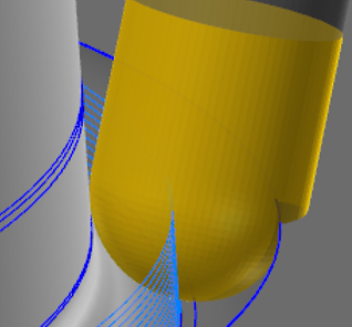
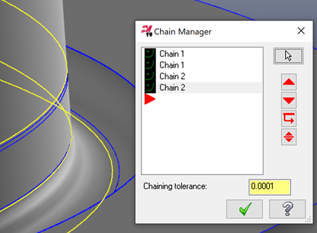
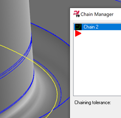
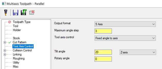
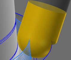
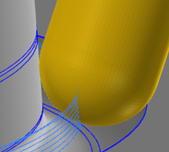
Heyo Kolson, I took a quick look for you. Right off the hop a few things jump out at me. 1st is that you're not going to be able to cut this all the way with this tool, as you see it gouges into the back side of the material: 2nd is that you've over-complicated it a bit as you might have guessed Now, the retracts and such are related to your Collision Control settings: Which tell it to trim out collisions.. That leaves you with a big gap to get from where you would have started to have collisions to where you wouldn't, and your linking settings kick in from there.. But you'll eliminate a lot of the problems if you set up the toolpath right, so before we play with linking and collision control, let's recap: Cut Pattern > Curves: There's no need for this. Parallel is designed to take shape/chain/pattern and copy that across all of the surfaces you've selected, which means you're not sure which one it's using to project from with this selection.. Delete all but the last one: Tool Axis Control - There's no need to use lines here. It looks like you just want it to rotate around the Z axis, but 20° off. So instead of lines, set it like this: That says to just stay 20° off the Z. Now, when you regen it it, you will only have one approach and one retract, but of course, it's still gouging on the backside: But now you can figure out which tool you have to cut it with that won't gouge. Another thing you can do is turn on "check surfaces" on the Collision Control page and choose the back of the channel and the top surface, but of course that's not going to cut as deep: Take a look at Op #2. Hope this helps! TEST_CURL_-_ACE.mcam

-
This is the first I've heard of it.. If you can figure out steps to reproduce please send it in! I haven't been able to replicate it on my side while playing.
-
mastercam2020 OpenCL 1.2 What is this?
Aaron Eberhard replied to Jeff2005's topic in Industrial Forum
If everything else worked fine, it's not worth disabling hardware accell just to get rid of the OpenCL message. All it means is that your toolpaths won't process as fast as possible if you had that capability. Disabling hardware accell will cause all sorts of other issues with display and selection since you'll be running in minimum viable graphics mode. I'd recommend you re-enable the hardware accell if Mastercam will run on your machine with it, and just hit the "don't show me again" checkbox on the OpenCL warning. -
Mastercam Version - Windows version Compatibilty
Aaron Eberhard replied to Mick's topic in Industrial Forum
Eh, I'd give it a go If you have the install media, it's worth a shot, but like GCode said, the big problem is the hasp stuff. I can run V9 on a Windows 10 VM here, but that's only because of a nethasp. What I CAN tell you is that the official line is "that's not a supported combination." -
Mastercam Version - Windows version Compatibilty
Aaron Eberhard replied to Mick's topic in Industrial Forum
Wow, that's a good one.. I don't think you can turn back the Windows 7 Compatibility settings far enough to make that work? I'd be tempted to try running in DosBox (the emulator), but you'll have to have a nethasp to connect to as I don't think Parallel port keys will work with it. You might have some luck emailing in to tech support, as there's a few people over there have been around since the V6 days -
mastercam2020 OpenCL 1.2 What is this?
Aaron Eberhard replied to Jeff2005's topic in Industrial Forum
Not quite.. Starting with 2020, we're trying to offload some processing to the video cards, which is done via OpenCL if you have it. So if your video card supports it, it might make a difference in your processing times if you upgrade your drivers to support it. See the KB article I linked to for a bit more information and help troubleshooting. You may be thinking OpenGL, which is the graphics processing we rely on for 3d graphics, you're correct that we require the same version of OpenGL for both 2019 and 2020. Yeah, it's confusing GL for Graphics CL for Computation. -
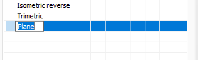
If it helps your sanity at all, I did confirm on my system that right click > rename immediately lets me type in the name: I tried it in 2019 and 2020 and works for me
-
Cutter Comp Beginning on Arc Move - How to Avoid?
Aaron Eberhard replied to Bill H's topic in Industrial Forum
Yeah, as other have mentioned, that's called the Binary NCI which is what I prefer to work in for my line of work The BNCI is pure code that comes from the toolpath, so it's as machine agnostic as you're going to get. ASCII NCI (what you get if you hit the "post" button and tell it to output NCI) is flavored based on what your machine settings are. Posted code is just the ANCI being formatted formally by your post processor. So for your sample code above, use the ultra-secret (documented in the MP post editing manual, I believe) CTRL+SHIFT+Right Click on the operation, you can choose "Display Binary NCI" (I prefer without line numbers, but you do you), and see if that call is being output on an arc. If it's not in the BNCI, then your post is adding it to the ANCI for you for some reason. -
Cutter Comp Beginning on Arc Move - How to Avoid?
Aaron Eberhard replied to Bill H's topic in Industrial Forum
Hmm, that's odd.. You should have no cutter comp at all until the finish pass? I just created a Ø.5" circle with a Ø.125" cutter, wear comp and roughing is turned on: When you look at the code that's created: G1002 0 100 10 1 1 1 0 2000 10. 0 0.87876113 0.26475797 0.5 10. 10. 10. 0 0. G0 0 0.87876113 0.26475797 0.5 -2. 0 G0 0 0.87876113 0.26475797 0.1 -2. 0 G-96 G-11 START DISPLAY TYPE - Entry G3 0 0 0.87876113 0.26475797 0.98562949 0.29990628 0.06295512 10. 3000 1 G3 0 0 0.87876113 0.26475797 0.98562949 0.29990628 0.02591025 10. 0 1 G3 0 0 1.09249785 0.33505458 0.98562949 0.29990628 0.00738781 10. 0 0 G3 0 0 0.98562947 0.41240628 0.98562949 0.29990628 0. 10. 0 0 G-12 END DISPLAY TYPE - Entry G3 0 0 0.98562947 0.41240628 0.98562949 0.29990628 0. 10. 0 1 G-11 START DISPLAY TYPE - Trans G3 0 0 0.98562951 0.18115628 0.98562949 0.29678128 0. 10. 0 0 G3 0 0 0.98562949 0.42490628 0.98562949 0.30303128 0. 10. 0 0 G-12 END DISPLAY TYPE - Trans G3 0 0 0.98562949 0.17490628 0.98562949 0.29990628 0. 10. 0 0 G3 0 0 0.98562949 0.42490628 0.98562949 0.29990628 0. 10. 0 0 G-11 START DISPLAY TYPE - Exit G3 0 0 0.92312949 0.36240628 0.98562949 0.36240628 0. 10. 200 0 G-12 END DISPLAY TYPE - Exit G-11 START DISPLAY TYPE - Trans G1 0 0.98562949 0.29990628 0. 10. 0 G-96 G1 0 0.98562949 0.36240628 0. 10. 2000 G1 41 1.17312949 0.36240628 0. 10. 0 <------- Cutter Comp starts with "41" > G-12 END DISPLAY TYPE - Trans G-11 START DISPLAY TYPE - Entry G3 0 0 0.98562949 0.54990628 0.98562949 0.36240628 0. 10. 1000 0 G-12 END DISPLAY TYPE - Entry G3 0 0 0.98562949 0.54990628 0.98562949 0.29990628 0. 10. 100 1 G-11 START DISPLAY TYPE - Exit G3 0 0 0.79812949 0.36240628 0.98562949 0.36240628 0. 10. 0 0 G1 140 0.98562949 0.36240628 0. 10. 0 <------- Cutter Comp end with "140" > G1004 G-12 END DISPLAY TYPE - Exit G-11 START DISPLAY TYPE - Trans G1 0 0.98562949 0.29990628 0. 10. 200 G-12 END DISPLAY TYPE - Trans G0 0 0.98562949 0.29990628 0.5 -2. 0 G-3 EOS - end of nci section You can see that the arcs helixing down don't have cutter comp on the raw generated passes, it's only on for the last pass. You should probably post an example file.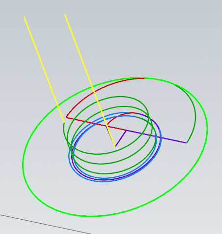
-
Tools for fixing old corrupted MCX files?
Aaron Eberhard replied to SlaveCam's topic in Industrial Forum
Good call on this, G. I forget what version (x7?) that every chain selection started remembering your chaining settings. That was a nice improvement. -
Also check out the Tool Axis Control page on Thread Mill and Helix Bore
-
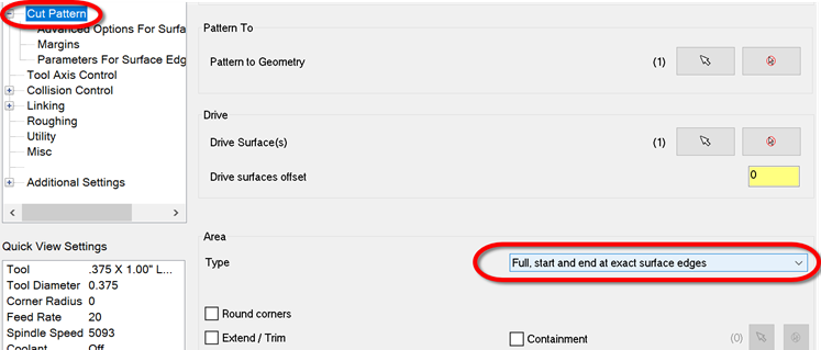
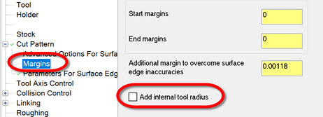
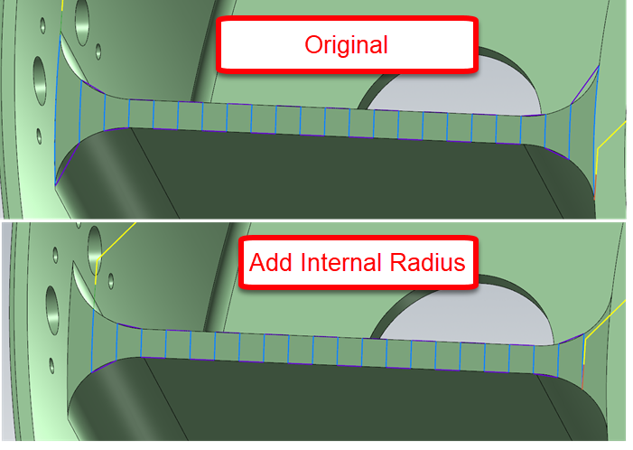
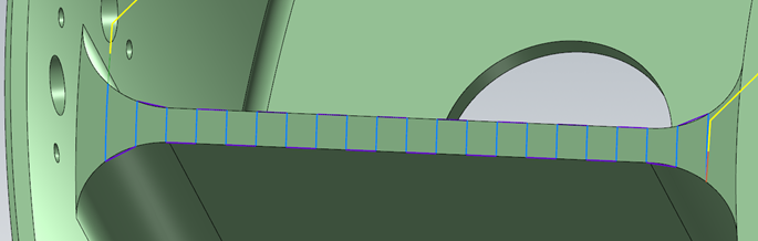
This one is easy with Morph once you know the "trick," which lies here: The toolpath as uploaded is set this way, which is cool because it gives you access to the Margins page like Mayday said. Turn this on: Now your toolpath will look like this: On a part like this, I can't see any reason to create any geometry at all. Working directly off the solid, I got this: Looks the same? Add in a bit of Cut Pattern > Extend and a Linking set to Blend, and now it looks like this: All without creating a single bit of geometry. Hope this helps!
-
Threadmill Operation Bug? WIerd quirk
Aaron Eberhard replied to Metallic's topic in Industrial Forum
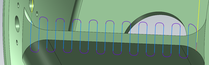
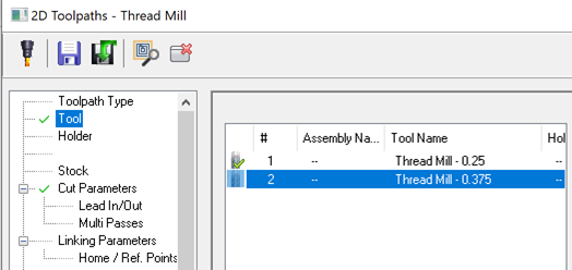
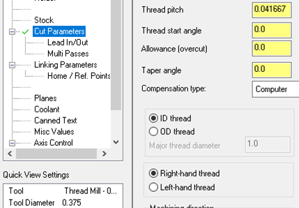
Sorry, I just re-read this, and I don't think it's the same thing that was discussed previously. Can you send a file into QC including which version you're experiencing this in? I can't replicate your behavior from scratch. I tried in 2019 & 20. Here's how I did it. I set up a Threadmill op on a Ø.500" circle, and defined a Ø.25" 24 TPI single point thread mill. I then copy/pasted the toolpath, edited the tool to increase diameter to .375" and the tool number to 2, while still leaving a 24 TPI and 1/24th as the flute length: No matter what I do, my cut parameters don't update: What did I do wrong?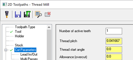
-
Threadmill Operation Bug? WIerd quirk
Aaron Eberhard replied to Metallic's topic in Industrial Forum
Hello Metallic, We discussed this back in February @ -
selecting multiple holes of the same diameter
Aaron Eberhard replied to pip's topic in Industrial Forum
If you're working directly off the solid, there's not a lot of options that make it easier in 2018, unfortunately. If you have access to Multiaxis Drill, then you can select "features" (solid holes). Hold down the CTRL key when you click to get all matching diameters. The easy button here is to use 2020 If that's possible to install the beta, give it a test drive. All hole making toolpaths use a new interface and you can just CTRL+Click to get all matching diameters, or CTRL+SHIFT+Click to get all matching diameters on the same vector as your selection. If that's either of those aren't an option, your best bet is to use Model Prep > Hole Axis. CTRL+Click on the solid to select all matching radii. Then, turn off the Points, Lines and only leave the Circles at the Top for Hole Axis. That'll give you a bunch of arcs at the top of your holes. Now, when you're in Drill, you can use Mask on Arc to select only matching radii. -
Just saw this.. We have this in the system as D-35180, it was just reported to us a few months ago, surprisingly. It affects all versions with the panel interface (2018, 19, 20). It's on the list
-
We use those (or one of the similar part numbers) here with good results.


