


Aaron Eberhard
-
Posts
1,406 -
Joined
-
Last visited
-
Days Won
103
Content Type
Profiles
Forums
Downloads
Store
eMastercam Wiki
Blogs
Gallery
Events
Everything posted by Aaron Eberhard
-

cannot get morph between 2 curves to undercut help!
Aaron Eberhard replied to lowcountrycamo's topic in Industrial Forum
That option can be valid even with a lollipop tool. In this case, what you really want to do is check the shoulder (and shank?) of the tool, so that the collision control is aware of the real tool shape and isn't gouging the shoulder into the part. It will then extend only the last part (shank) to infinity. You may also want to "move tool away" "Along surface normal" instead of just trimming if there's a collision. -
You're welcome. To reverse it, on the Cut Pattern page look for "Flip cut order" under "Sorting."
-
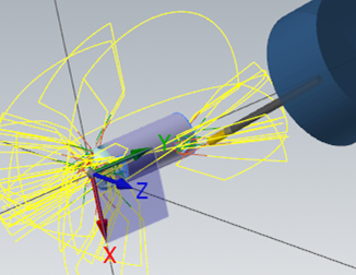
Heyo Spotterhphc, I took a quick look at this because it seemed like it would be more fun than doing real work I modified op #7, your Parallel toolpath. Stock - Use Stock Model #1 (Op #3) Cut Pattern - I hooked it up to the level 4000 geometry and set it to be Parallel to Angle so I got a constant step down. Tool Axis Control - Fixed Angle To Axis, "X." This will make it a "3 axis" toolpath, i.e., it will make the tool axis control independent from the geometry. Collision Control - CC#1 - Tilt Tool Automatically against the drive surface and the check surface (the flat bottom floor). This will cause the tool to tilt if you're going to hit the drive surfaces, modifying what we set in Tool Axis Control. Roughing - Multipasses turned on. I did 6 passes @ .1 depth, but of course you can use whatever you need here. The idea is to make sure there's enough passes that the excess can be trimmed off by stock. Multipasses will offset from the surface, Depth Cuts would have offset along the tool vector. I didn't play with Linking, but I would probably put a lead in/out on so you don't just plunge directly into the material anywhere it's trimmed. That gives me this as an output: Hope this helps! MULTI-UNDERCUT_-_ACE.mcam
-
Cool, I hope it helps you out
-
Yeah, it's the classic "I want it to be smart enough to look at the tool!" "I don't want it to look at the tool anymore!" dichotomy that we always seem to run into. In ideal-land, we would always be able to instance darn near everything from the tool & material information. In reality-land, there's plenty of places where you want to override it. The problem that we have in an instance like this is we can detect if you've changed it and never change it again, but what happens when you select a completely different tool. Would you have wanted it to update in that case? Yeah, probably. What about in the case where you've saved it with a value, but you're importing the toolpath and re-selecting geometry and tool? Etc., etc., etc.. So to be predictable, if you reinitialize the tool at all (re-selecting it, changing parameters, etc.), then update the settings. It's one of those fun no-win scenarios
-
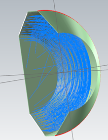
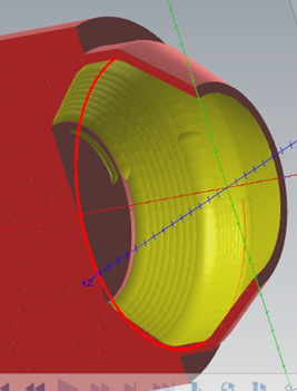
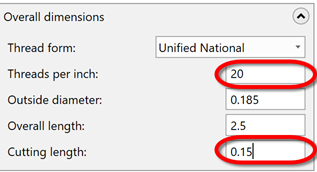
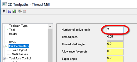
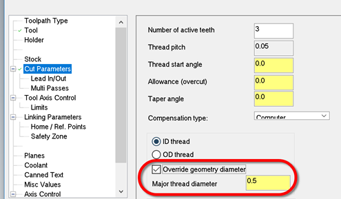
Yes, this is what it's supposed to be doing. The cut pattern page reads the tool data to determine how many threads are active, which is defined by the thread pitch and cut depth: = If you change tools or even click on your tool again, it will reinitialize that Cut Parameter page setting. If you never take advantage of using a multi-point threadmill, I would suggest that you define your tool with the cutting length set to one tooth (in my example above, that would be .05 or 1/20). Check out 2020 then:
-
Yep, as Old_Bear mentions, your standalone Mastercam license allows you to install and run MCfSW as well. Well, assuming that you're using 2017 and up (I think that's when the change was? Time is blurry thing..). You might as well take it for a test drive since you already own it!
-
Lookin' great, Husker!
-
You may want to look into "change recognition" if you haven't before, Metallic. Obviously, there's limitations if the changes are too great, but it will often work very well if all of the solid faces still retain their original IDs and such.
-
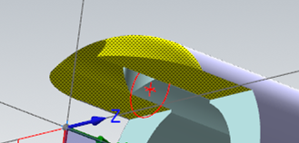
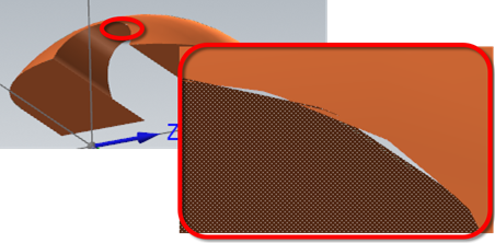
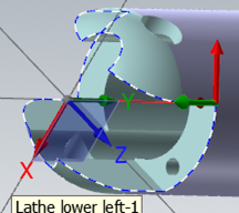
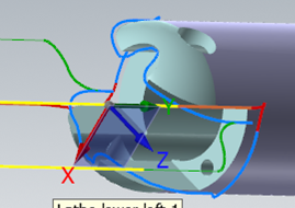
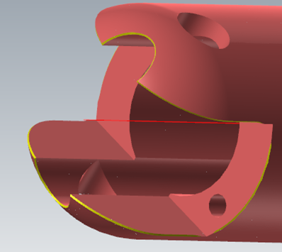
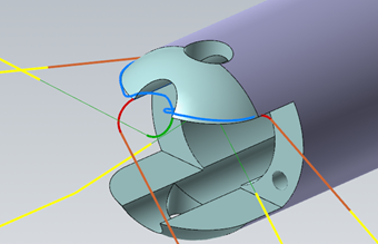
I took a look at this file, and I don't think you're going to have success the way you've defined the faces and such. The way this toolpath works is to figure out a sharp edge from what you give it. Unfortunately, with just these two faces, there's more questions than answers Think of this as if you had made a model with just those two surfaces (create surfaces from solid, for example). This is what you're feeding the algorithm: Eww. A better way to go about it is to just select the entire model. I wasn't sure which toolpath you were dealing with, so I just chose the last one, #20. I unselected your two faces and just selected the whole model which gave me this: It looked like you were really just trying to trace the slot edges, so I chose those as my "User defined" edges: I also set it to 3 axis, because I believe that's what you were gunning for? As a side note, there were lots of improvements to Deburr in 2019 Update 3, so I'd encourage you to use that if it's available. There were heaps more in 2020, so that'll be the choice once it's in public beta. Here's 2020, all I did was open the file and regen Op #20: Hope this helps! sleeve2 - update.emcam
-
Since X9 all of the 5 axis paths have worked in WCS. That doesn't mean that there's not a defect here or there, though If I recall for this particular part, we got bit by some changes made to the planes sub-system early in 2019. A lot of the stuff we build on the toolpath side relies on referencing planes, of course. We just didn't have this particular test in our automated test suite (a flow 5 axis in a non-top WCS with tilt set to lines) so we didn't catch it. We have it in there now, though!
-
2020 at this point. It missed the boat for 2019.
-
This sounds like a defect recently reported to us (R-17720) that we just fixed.
-
multiaxis toolpaths locked to 3 axis on HMC?
Aaron Eberhard replied to motor-vater's topic in Industrial Forum
In general, Parallel will often give a better toolpath than Triangular Mesh, just based on the underlying technology. The equivalent of "constant Z" is to use Parallel set to "Angle" (as in, "the path will be parallel this angle"). Of course, you can always convert it into a spiral instead of an actual constant z, water-line style toolpath just like you can with Triangular Mesh. -
multiaxis toolpaths locked to 3 axis on HMC?
Aaron Eberhard replied to motor-vater's topic in Industrial Forum
Right. Remember that any reference to an axis (X,Y,Z) in a multiaxis toolpath is relative to the WCS of that toolpath (in your case, TOP), to elaborate on why Mayday is correct. The "Front, Front" part of your plane selection really has no bearing on anything here. In the case of your clearance plane when you're programming Top, Front, Front, you're retracting along the Y relative to the Top WCS, NOT the Z. If you were on the Top, Back, Back, you may need to retract -Y, for example. Right & Left would be along the X. -
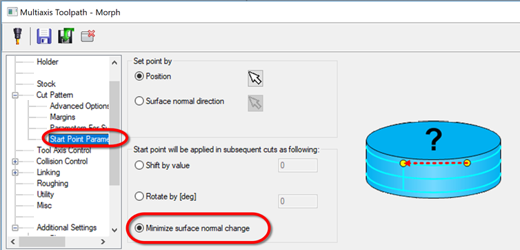
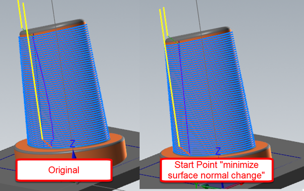
The reason that it's doing this is that it's approximating the start point as half way around each pass (as you've chosen with your start point selection). It doesn't realize that you don't actually want that, you want to follow the surface UV (the grid that makes up the surface). There's an option that does this, but it's apparently not enabled when the Morph toolpath is set to "exact" algorithm. I'm not sure why, I'll have to look into it. In the meantime, if you go back to the old algorithm (Cut Parameters > Advanced Options... > Step Over Calculation = Approximate), then look on the Start Point page: That'll give you this: Hope this helps!
-
Back in the day, I used to have the same issue in Autodesk Inventor and Autocad(?) Perhaps it was Autocad Architectural or Mechanical? I can't remember which specifically. That was a long time ago . I haven't gotten to run inventor in at least 10 years and Autocad for much longer than that, but that's what let me know what to look at when I started selling Mastercam and ran into it with a customer's install.
-
Imported models can carry color info with them (depending on import format). I've always had good luck by first using Model Prep > Clear Feature before trying to change the color of those.
-
I've had to uninstall the Microsoft mouse driver before because no matter what I did it always zoomed out at an uncontrollable rate. I haven't ran across anyone with the Microsoft drivers installed in a few years, though, so I'm not sure if it's still the case. After I uninstalled it, everything would work normally. The drivers didn't add any functionality, either.
-
I'm a big believer. I'm a fan of changing the default behavior of the 3d connexion ones to Zoom Direction - Up/Down instead of Forward/Backward. In observing a lot of people I trained, it seemed more natural. Change my mind As far as model goes, if you're just starting out and paying for your own, it's worth the money to just grab the two-button "spacemouse," to make sure you're going to use it. If it's not your credit card, I'd recommend the Pro (the model without the LCD). Perhaps others have a different opinion, but I have a few-years-old model with the LCD and I don't think it adds anything. I'm already staring at enough screens, I don't need to look down at my mouse to see another! Edit: As for Motor-Vator.. Well, some men you just can't reach
-
Correct, or at least, the vast majority of 'em. There are a few controls out there that will actually accept a 3d arc as input, but honestly the applications where it improves anything are extremely niche.
-
Using more cores for multithreading
Aaron Eberhard replied to So not a Guru's topic in Industrial Forum
There's two things that you may be thinking of. In Multithreading manager, you can specify the max number of THREADS (not cores) to run simultaneously, i.e., if you hit regen on 8 toolpaths, it will only process 4 at a time. Now, those toolpaths may be multithreaded and using N cores, but that's up to Windows to manage. You can turn it up or down, but you're unlikely to see benefits, as processing more toolpaths at a time means less system resources are available for each toolpath in the hopper. Now, if you wanted to actually limit how many cores Mastercam can use, you'll have to do that through the Task Manager. Go to the Details tab, find Mastercam and right click. Choose Set Affinity, and the box will pop up. By default, Windows allows us to use all cores available, but you can turn some off if you had some desire to (another CAD program needs some dedicated resources, toolpath regen is making your youtube cat videos skip, etc.). -
‘Blended’ spline pattern, how to achieve?
Aaron Eberhard replied to Carbonwerkes's topic in Industrial Forum
From the picture, I'd look at your linking parameters for that toolpath. It looks like it's trying to keep down between regions. Of course, best would be to post the toolpath, but it looks like you're not trying to contour/morph from the outer shape? In that case, you may have better luck with a Parallel toolpath, since that will offset one shape across the whole part. -
‘Blended’ spline pattern, how to achieve?
Aaron Eberhard replied to Carbonwerkes's topic in Industrial Forum
The key (which is only obvious in hindsight) is to create a Lofted surface, NOT a Flat Boundary surface. If you do a Flat Boundary there, it'll create a square surface and "cut" it out at the splines. The surface UV lines are still going left-right in that scenario, meaning that the curves that follow it will also be parallel. When you create a Loft, it's creating a surface that stretches from one spline to the other, so the UVs are going to be a transition as well. You can see this if you switch to wireframe mode after you create the surface. -
Select rectangle corners for drill operation Mastercam 19
Aaron Eberhard replied to TimW's topic in Industrial Forum
You're welcome sir. Glad to hear it!

