Aaron Eberhard
-
Posts
1,406 -
Joined
-
Last visited
-
Days Won
103
Content Type
Profiles
Forums
Downloads
Store
eMastercam Wiki
Blogs
Gallery
Events
Everything posted by Aaron Eberhard
-
Unless you switch to translucent view.. In X9 (and forward), you have to be able to see it to select it, so you can either rotate your part or just goggle translucency.
-
This always seems like such a financially horrible idea to me.. Who decides that they don't want their employees operating more efficiently? Training is one of those things that makes an employer such a better place to work, too.
-
Under Focus on the main toolbar you can choose to focus on the tool, workpiece or multiple workpieces. . If you choose tool focus, the tool stays stationary and the part will rotate. if you choose workpiece, the part will stay stationary and the tool will move. With that being said, Verify does not know the kinematic layout of your machine, so if there's a work shift of some sort in effect, or any other mitigating factors will make it not accurate to true machine motion.
-
He's been working on it with them. I don't know if it'll be out with 2017 or an "add-on" download at some point..
-
Thanks for covering the Multiaxis side, Colin.. Our own toolpaths also support barrels & feed mills, look for anything in the "3d" toolpath area ("Surface" toolpaths in X9) to use them except for flowline. Both roughing and finishing. They should even be working correctly to undercut with the Contour toolpath. Just a note that a LENS setup is really not a barrel mill, it's more a high-feed mill, but man is it ever fuzzy where that line crosses over!
-
Yes, there are customers out there running this exact config. We also have people down at the THINC center (Okuma's USA corporate HQ) in Charlotte running it, so their AEs are getting better with it as well. Cheers,
-
It's not a dumb question at all! This is a really, really complicated subject, with a lot of gotchas (I discover new ones every day it feels like ) Yes is the answer, but with TCP it "doesn't matter." Next time you're at a show, walk past the pretty new machines with their super-fast rotary axis and smoooth Heidenhain controls, and you'll see that whatever demo part they're doing is constantly rotating/flipping the C axis 180° as it passes over perpendicularity. There it is! Singularity is really a function of what happens when you get the rotary axis perpendicular to the spindle, TCP won't change that part of it. On the older controls without TCP, those big C axis moves wouldn't be compensated correctly in between the vectors (i.e.: the position X Y Z C90 would be correct, and X Y Z C270 would be correct, but the traversal from the first to the last wouldn't be synchronized to keep the tip at the right place), so you'd gouge pretty bad in between those points, but your "start" and "end" positions would be correct. Now-a-days, if you're trying to machine efficiently, you'll still want to spend some time trying to avoid those rotations, but at least you won't gouge when you have them anymore, it just wastes some time and can affect the finish a bit.
-
You'll like it Listen to what David says above about making sure your post is up to snuff, and keep in mind depending on your geometry & machine kinematic layout, you can hit singularity pretty easily, since you're taking a 3 axis toolpath and then only tilting when needed, you're often near perpendicularity. It's the same as any other multiaxis toolpath, really, but easier to get into that condition since you start there.
-
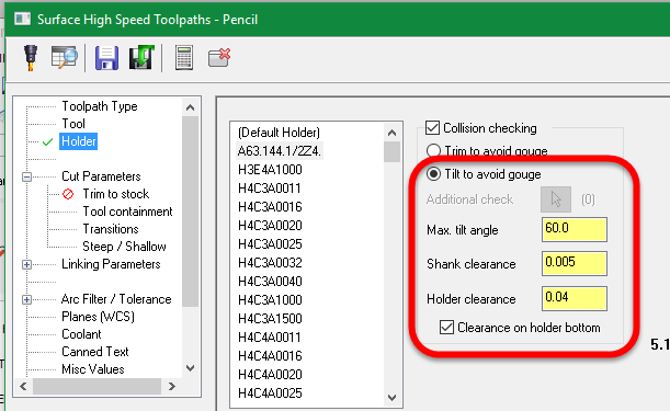
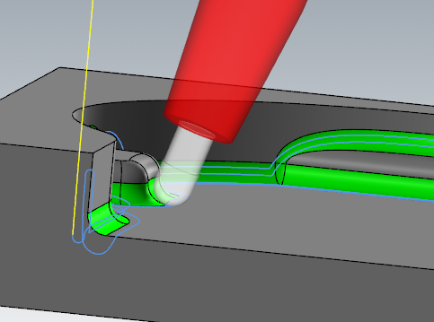
Did I miss the reason you can't just use the high speed pencil toolpath and turn on "tilt away to avoid collisions" on the holder page? That seems like the easy button to me, but I just skimmed this thread..
-
No, the syncing is by length. 50% of the top spline is synced to 50% of the bottom one, etc.. It's not even affected by node-point density, which is nice. The only way to sync otherwise is to use tilt lines.
-
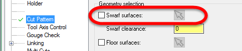
Interesting discussion, guys, thanks I'm going to mostly stay out of it, but I will be mining it for info... I just wanted to pop in on this one: That's actually incorrect, but not obvious. The reason it looks like that is because the strategy is set to Automatic, which relies on using the surface/mesh information to calculate the correct (or what it guesses is the correct) orientation and position. If you choose a different strategy, like say, sync with tilt lines or sync with curves: You'll find that you can now uncheck your drive surfaces: Hope this helps. Cheers,

-
You're welcome, David. The lathe-based machines are definitely not forgotten, and you should see it supported quite soon, so don't worry too much about that one I understand that the post will stop you from actually posting code with mill and turning tools linked together (hopefully... in most cases...), but I was just trying to illustrate some of the things that we have to look at before stamping an "OK" mark on a feature. Even if the post won't allow it, or it's not physically possible on a machine, imagine how frustrated a user would be if Mastercam "allowed" something like that, but they couldn't post. Please let me know how you like the new features when the public beta is out for the next release. Cheers,
-
Hey Daniel, Sorry about the delay, I've been working hard down here in the software mines, so I haven't had been up to the surface to check up on this. You know I have massive respect for not only your accomplishments & knowledge, but how well thought out all of your arguments are. I don't have time to get into specifics on our MT solution vs others, nor is this the appropriate place. I will say, though, that we have very passionate and motivated people in the right places here and, like computers, development of software never can go fast enough. I think it's on the right trajectory. I really just took umbrage with your statements: I think I had a pretty legitimate reason to keep it out of the lathe based machine defs for X9, namely that I want to make sure my department is putting out high quality and reliable software. I didn't feel that I could meet that goal for Multiaxis Link in the time we had available, so we didn't release it for that duty. I also don't feel that anyone here is specifically "fine" with being behind the competition in any arena. We're a generally pragmatic bunch, but I don't think that being pragmatic about the reality of how difficult and long it takes to develop software is the same as being fine with it. I look forward to talking about this over a beer some time
-
Hey Jaz - As you know, "Classic" swarf has a defect when locked to 4 axis on a custom WCS (D-17984 if you're playing along at home) that the boys in the back room are looking at as we speak, so I'm hoping to have it fixed soon. There's currently no way to lock the new Swarf Milling down to 4 axis, although that is on the future plans. Unfortunately, the only way to use a swarf toolpath locked to 4 axis only is to go back to the old method (pre X9) of moving the part back to the top view. The good news is that you can generally use a Parallel to Curves toolpath and get the same motion as a Swarf, so I'd give that a go if you're in a pinch and don't want to move your geometry (and, let's be honest, who really wants to move their geometry!?). Cheers,
-
That's a overly pessimistic view, Daniel David - Sorry to cause you grief. The real reason was with all of the different combinations of planes, tools, and axis combos, I wasn't comfortable releasing the first go of Multiaxis Link on that platform. I knew that anyone using a multiaxis Mill would be able to run it, and I wanted to see how it performed in the field before adding all of the safeguards necessary to keep people from hurting themselves in the Lathe environment (why can't I link a turn profile op and 3d milling op?). Just a note, I don't get over here as much as I'd like but there was recently a thread on our forum about this, and I'd be happy to chat about it whenever you wanted. Cheers,
-
Hey Jaz, I just saw this thread, so I had a chat with the Tech Support guy you had emailed with. He had a misunderstanding about what was going on. This is a defect that we are currently looking into, and it should work correctly the way you had it (except that you would need to rotate around the Y axis, not the X in this case per your WCS orientation). This only affects these toolpaths locked to 4 axis and using a WCS other than TOP. Unfortunately for the moment there is no work around in X9 other than to position the part correctly relative to the TOP WCS. I'm hoping to have it fixed soon and then to port it back to X9 at the next update. If you want to follow along with its' progress, reference bug D-17984. Sorry for the inconvenience. Cheers,
-
I'd be cautious of running it (or any 5 axis program) near A0 on a control without TCP. On a Table/Table design like that (or a Head/Head for that matter), you can run into singularity problems when the primary rotary gets perpendicular to the spindle, so your C axis (most HAASes call it a B for some reason?) can experience large moves. Normally this isn't a big deal, but without TCP, you can gouge the part when this happens because the control doesn't compensate the tool tip while traversing the vector. Use all of your normal multiaxis programming techniques on that machine, like mounting it to a sine plate so that when the part is "flat," the A axis is actually at 10° or whatever and doesn't pass perpendicular to the spindle. So, in summary, use all normal caution you would with any other 5 axis toolpath on this machine, but the "tilt away" function works great
-

Nvidia Driver for Mobile Workstation
Aaron Eberhard replied to dfedwards's topic in Industrial Forum
Indeed, it's hard to stress it with 2d apps -
Glad to hear it! Foggy - I'm trying my best to look out for you guys
-
Yeah, I agree that most of the I+ operators struggle until they get their head around P+. P+ and I+ can also step on each others' memory locations/calibration info as well. Unfortunately, according to Renishaw, consolidation is not going to happen. There's too much divergence between the two, and too much customization that happened for each manufacturer's variant of I+. That said, we're aware of what you guys are going through, and I'm working with Renishaw to come up with better, more unified solutions, but it's not going to happen for a while. What I would expect to see is the next generation of P+ and I+ use the same macros, and Renishaw calls the program <whatever>+ with a gradual transition away from both I+ and P+. Changes like that don't come quick, though, and I make no promises/projections for when something like that would come about. Cheers,
-
Hey Matthew, You shouldn't have any trouble getting a report to compare those two points, whether you would want it as an angle (relative to vertical Z) or as a difference between two points. Shoot me an email and I can help get you down the path with that one. I think you've emailed me before, but if not, send me a PM and I'll give you my contact info. Cheers,
-
Nvidia Driver for Mobile Workstation
Aaron Eberhard replied to dfedwards's topic in Industrial Forum
Yeah, if you're looking for actual tuning/diagnostic info/whatever, there's other programs for that. This one is only for laptops that use the Intel/Nvidia combo video cards, that tech called "Optimus" uses the intel for light-weight work like web surfing, excel, word, etc and then will kick up the Nvidia when it's time to do 3d work. In theory. I've had my laptop for a few years now (dell precision M6700) and I had some trouble with the earlier drivers where it wasn't using the correct graphics card even when I specifically said to, and it drove me nuts trying to figure out what was using which card until I found out about that. They do this for heat and battery life. If I don't have any 3d program open, I can get almost 7 hours out of my laptop, but if I open any 3d program, it'll be maybe 2.5. That's how much juice the Quadro uses. -
Nvidia Driver for Mobile Workstation
Aaron Eberhard replied to dfedwards's topic in Industrial Forum
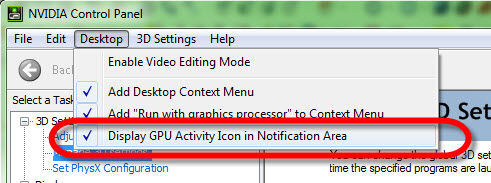
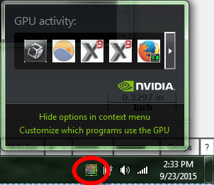
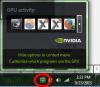
With Optimus, I've had trouble getting the new drivers to install correctly; try doing an install of nvidia's drivers while in safe mode and see if that helps. I always recommend doing the "custom" install and telling it to do it "clean" so there's no traces of the old drivers there. The other thing to do is on the nvidia control panel (right click > nvidia control panel) turn on "Display GPU activity in system tray." Now, you can go down and actually see what programs are using your Nvidia card while the program is running: Which is helpful to keep a tab on what's actually using your horsepower card..
-
Hey guys! Sorry, I just saw this thread, figured I'd hop in to help clear things up a bit. The first question (starting at machine home) is actually starting at TOP's XYZ 0 position. That's the classic backplot issue that's shown for Multiaxis toolpaths for years. Summary of it is: The tool has to be displayed somewhere in the TOP XYZ orientation, so it just puts it at the origin. It's annoying, but it's a limitation of the classic backplot. If you check it in the new backplot in Simulator, you won't see it, nor will you see it in posted code. The second question about the first cut size, looks like a defect, I'll have the lads take a look at it. The summary of this one is "Reduce the Ramp Length (under Roughing)." That'll shrink the helix size. Cheers,
-
You can program on solids regardless of whether you have the solids add-on or not. The solid add-on gives you the ability to create or manipulate solid entities, but you can still select faces, edges or the whole model without it. Either way, as FTI points out, there is no more solids add-on, starting with X9, it's rolled into the product, so anyone on maintenance has it.