


AHarrison1
-
Posts
580 -
Joined
-
Last visited
-
Days Won
7
Content Type
Profiles
Forums
Downloads
Store
eMastercam Wiki
Blogs
Gallery
Events
Everything posted by AHarrison1
-
I generally put mine just after the tool change. If your spindle is going the wrong way then yes switch M03 for M04. Below is an e.g. N31 (OD MAIN- 80 DEG) G18 G20 G40 G56 G80 G99 G00 G53 X0. Y0. T0 T131 G14 G40 G56 G80 G99 M155 M08 G50 S3500 G96 S450 M03 G00 X0.75 Y0. Z0.1 M08 M88 G01 Z0. F0.004 G1 Z0. F0.008 X1.0611 G3 X1.1194 Z-0.0121 R0.0413 G1 X1.2258 Z-0.0653 G3 X1.25 Z-0.0945 R0.0412 G1 X1.35 Z-0.0944 M89 G00 G53 X0. Y0. T0 M01 G15
-
Be careful using G14. It gives you the ability to program for the main spindle and then apply the g14 for sub which essentially mirrors the program. What you need to be wary of that the tools you use for the sub must be the same as those used for the main, i.e. left hand tools for both. Otherwise your sub spindle will be spinning the wrong way. Don't forget G15 to cancel
-
Just open the file in your version of choice and change your machine in toolpath parameter files and execute Even with an active toolpath group, when I merge it does not bring in the toolpaths only the geometry.
-
Yes, the latest and greatest. Although I am still using 2020. When merging it only brings in the geometry, If i drag and drop (to open) then it brings in the toolpaths. The only time I get an error is if the machine def and post do not match. I don't see an option in merge to bring in toolpaths.
-
I have just tested the Ctrl + drag to merge in 2021 with X5, X9, 2017-2020 files with no issues. Files merged as expected. I can't speak for nesting as i don't do/use it.
-
Ctrl + drag to merge, as of 2020 i think, the version does not matter if you are going from earlier to later version.
-

4 Axis Lathe - Ideas for Clocking Parts
AHarrison1 replied to mayu's topic in Machining, Tools, Cutting & Probing
To be quick and painless I would position your c-axis @ 90 then use a drill or pin the same size as the hole to get your part as close as possible then fine tune your c-axis adjustment with indicator. -
Watching some of these machines hurts my head sometimes.
-
Sort of like this?
-
A carbide drill with a drill length of 3xD and a peck of at least 1xD will work just fine. I have never had drill wonder on me while drilling OD.
-
It really does depend on the application. The only time I've come across a spot-face (chamfer) being important was for sealing off against an o-ring for high pressure hydraulics, and even then it was more the surface finish that was critical. If this is just to chamfer a tapped hole, the quicker the better especially for production purposes.
-
Why not look at drilling and chamfer in one? For example, https://www.walter-tools.com/en-us/tools/standard_products/holemaking/overview/drilling/xtratec-d4580/Pages/default.aspx
-
Carbide thru tool drill recommendations
AHarrison1 replied to Tinger's topic in Machining, Tools, Cutting & Probing
We have been getting good performance from Walter drills. https://www.walter-tools.com/en-us/search/pages/default.aspx#/holemaking?query={"r":[{"n":"WICTaxonomy","v":["holemaking"]}]} -
No no, he was right. It is 'since you paid...'
-
Lathe Groove (Chain) Smooth vs. Steps glitch
AHarrison1 replied to StevenL's topic in Industrial Forum
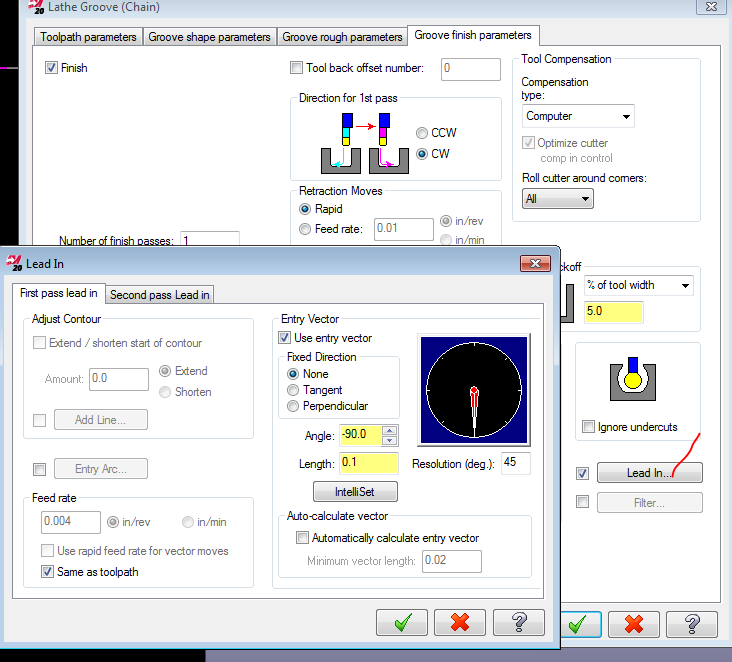
Seems excessive for a lead in. Another setting worth looking at is 'use stock for outer boundary' which looks at stock remaining from previous ops and minimizes air cuts.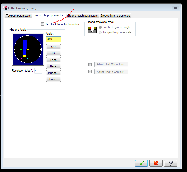
-
hitting space bar after clicking the anchor point maybe
-
In cases like that I program for both machines, just in case there has to be a machine switch. We have seperate file directories for each machine and all parts are named with the current rev # included.
-
Lathe Groove (Chain) Smooth vs. Steps glitch
AHarrison1 replied to StevenL's topic in Industrial Forum
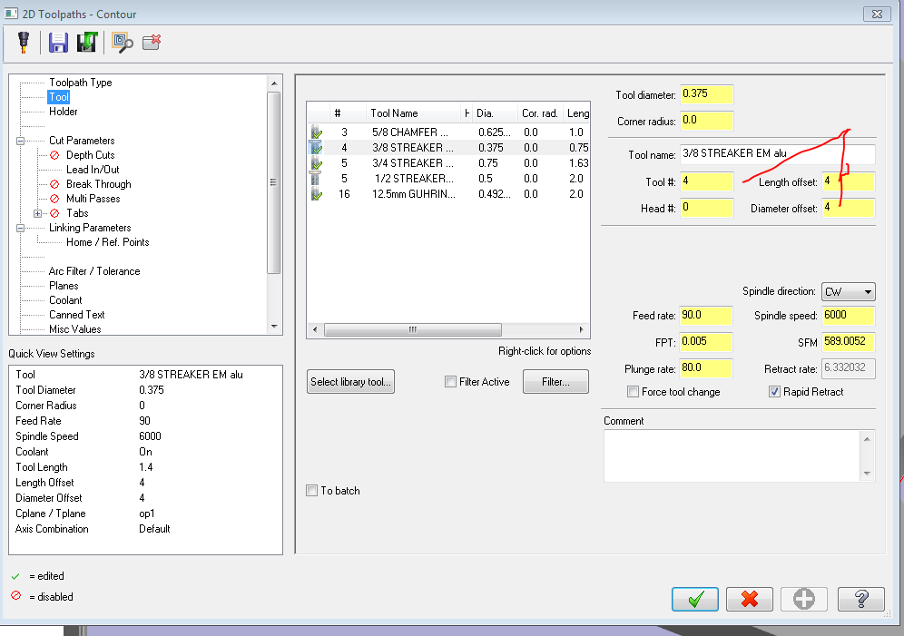
When i get issues like this I either tinker with the smooth parameters (pic1) Most of the time it is the lead in that I have to adjust (pic2)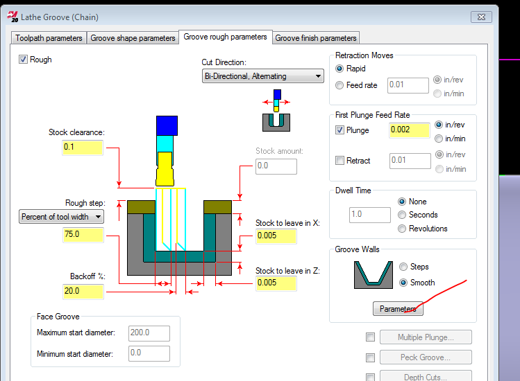
-
Yes, I have libraries for stainless, alu and tool/mild steels
-
I have created dummy files with the machine defs and relevant tool data base for each machine that i program for.
-
Create Note Changes System Level and Color
AHarrison1 replied to Snaglpuss's topic in Industrial Forum
I have just tested this on my system and it sticks within the same session and does not change my current active level or colour I also tried applying the settings through file configuration and have found that it does not carry over to other/new sessions. I would say you might have a bug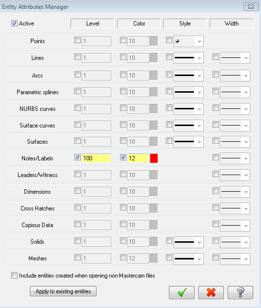
-
There is another way to aproach the programming by replacing the G2/G3 with G1. In order for it to be accurate you would have to know the intersection co-ord of the straight sections and then have enough room for the rad to complete Normal point to point: G0 X1.0 Z.05 G1 Z-.25 G1 X1.25 G1 Z-.5 With rads G0 X1.0 Z.05 G1 Z-.25 R.03 G1 X1.25 R.03 G1 Z-.5 i am thinking it's more to do with the age of the software than the machine. If I remember correctly X3 was extremely buggy.
-
What machine are you running this on Tom? i.e. machine age, controller etc
-
For the 1st part, make sure that when you are choosing your machine type that is 3-axis not 4- axis. The tool number is pulled from the tool library, this can be changed either in your tool parameter page or within your tool manager
-
Without seeing a file it will all be guess-timation. If you can include a zip2go of your Mastercam file it will help others help you.

