AHarrison1
-
Posts
580 -
Joined
-
Last visited
-
Days Won
7
Content Type
Profiles
Forums
Downloads
Store
eMastercam Wiki
Blogs
Gallery
Events
Everything posted by AHarrison1
-

Mcam 18...Can't move geometry to different levels anymore
AHarrison1 replied to Dontech's topic in Industrial Forum
In the feature tree that icon will show up on any model un-resolved. Failing all, do as JParis suggested and restart. Before doing that though make a backup of my mastercam folder then delete my mastercam folder. When you re-launch Mastercam it will rebuild the my mastercam folder. Something might have gone pear-shaped there
-
Mcam 18...Can't move geometry to different levels anymore
AHarrison1 replied to Dontech's topic in Industrial Forum
Just a FYI. You can open SW files in Mastercam without having to translate -
Mcam 18...Can't move geometry to different levels anymore
AHarrison1 replied to Dontech's topic in Industrial Forum
Look for the traffic light at the top.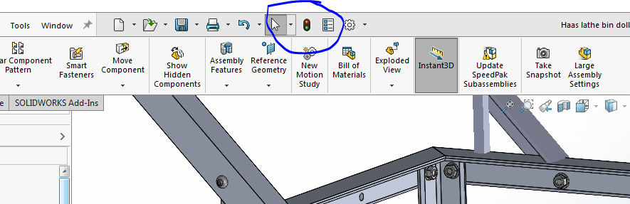
-
Mcam 18...Can't move geometry to different levels anymore
AHarrison1 replied to Dontech's topic in Industrial Forum
Could be that the Solidworks file was saved in an un-resolved state. Maybe reach out to your eng team and ask if they can re-build then save. -
That is correct. I would also back up the shared folder as well as this contains machine defs and posts.
-
I may be wrong here but does the statement not have to read G103 P0 to cancel? This is how it is for our DS30y. Although, in all honesty, I haven't tried it without the P0. I hope this doesn't come across as too condescending... seems to be a common theme lately. Nevermind, found the answer. It can be either/or https://staging-diy.haascnc.com/g103-limit-block-look-ahead-group-00
-
This what you are looking for?
-
Index Drill as a drill and boring bar (MasterCAM)
AHarrison1 replied to StevenL's topic in Industrial Forum
in fact anything in C-axis, drilling or milling shows stock removal when verifying. Your initial stock creation will have to have a hole the same dia as your drill put into it. -
Index Drill as a drill and boring bar (MasterCAM)
AHarrison1 replied to StevenL's topic in Industrial Forum
Nothing wrong with having 1 tool and two different offsets. The only issue will be in Mastercam. I have found that when face drilling in lathe it does not remove the stock, so when you go in to bore with your next op you will probably get a tool crash alarm as it does not see enough clearance for the bore bar. This is why I suggested keeping it as 1 tool. When you profile the Drill diameter Masercam will then recognize the stock as being removed...if that makes sense. -
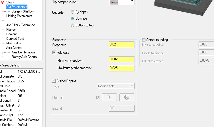
You need to play around with these settings
-
Index Drill as a drill and boring bar (MasterCAM)
AHarrison1 replied to StevenL's topic in Industrial Forum
Another solution would be to create a line drawn at the same diameter as the tool then that becomes your 1st machine profile. So instead of the 1st op being a drill cycle it is just a turn profile. You can then use the same tool and same offsets- 9 replies
-
- 2
-

-

-
- index drill
- boring bar
- (and 2 more)
-
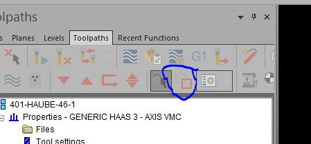
You could try dragging a window over them. In the AutoCursor bar (top middle of the screen, hit the dropdown arrow next to the dashed square, one of the options is in+ that will include everything that the window touches.
-
Lathe finish, end contour tangenting another line
AHarrison1 replied to SlaveCam's topic in Industrial Forum
I tend to put fillets / edge breaks at all intersections so, unfortunately, you would have to add geometry. I would add a rad just a couple of thou bigger than your tool nose rad between the red and blue lines then add that fillet to my contour.- 1 reply
-
- 1
-
-
If every time you launch MC and your ribbons come the way they are supposed to then it is saved already. Using the migration wizard generally brings in your work space as you have set it.
-
finding center point of circle that doesn't have one
AHarrison1 replied to jonathan joseph's topic in Industrial Forum
I don't have x8 loaded but when I opened the file and analyzed each element they came as as lines, not splines. So nothing to simplify there. It looks like you are going to have to draw your own circles. The easiest way I found was Circle Edge point then 3 Points tangent then pick any of the 3 lines making the 'circle' -
finding center point of circle that doesn't have one
AHarrison1 replied to jonathan joseph's topic in Industrial Forum
Look for a button that says 'Simplify Spline' which will convert them to arcs. I think this will only work if it's a closed spline thus creating a closed arc / circle -
Sounds like it could be a good enhancement. Maybe along the lines of if a solid surface / face is picked a copy of that surface is saved to some or other level specifically for use with that button.
-
Could be the show associated geometry
-
finding center point of circle that doesn't have one
AHarrison1 replied to jonathan joseph's topic in Industrial Forum
See below thread, might help you out Oops my bad, missed the part about it being X8. -
Dynamic Milling on 316 Stainless Steel
AHarrison1 replied to Tim Sureline's topic in Industrial Forum
For 3/16 - 200 sfm .0012 FPT For 1/8 - 200 SFM .0008 FPT Do you use 12% step over in Aluminium? I will use that for SS andcarbon steel, for ALU I generally use 30 - 40%. -
This, for me, is the beauty of Mastercam and I suppose machining in general. For instance, I'm not too savvy on the solids portion of Mastercam. I can do the basics like make an extrusion and put some holes in it but the push/pull, solids history etc,etc is mostly gibberish to me. Point is plenty of ways to skin a cat.
-
I made the 2 circles , then loft surface between the 2 circles. Created edge curves on the holes, edit trim/break the top circle to the outer intersections of the holes then flat boundary surface those. Refer to Levels 11 & 12 locating ring-a.mcam
-
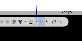
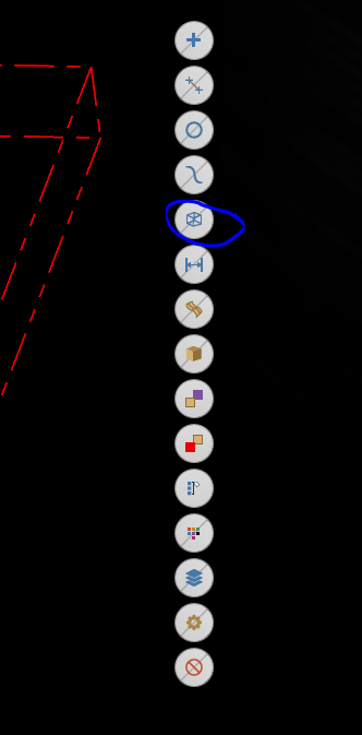
Try using the quick mask on the right of the screen. The one I have very crudely circled is for wireframe.
-
We don't rely on setup sheets all that much. Most of the info i need to pass on to the operator will be in the program itself, i.e. (pick up back left, Z 0 is top -0.02") My most common instructions/info I have saved in a word document from where I can copy/paste into the program.
-
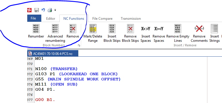
I am only aware of removing line #'s