Leaderboard


Popular Content
Showing content with the highest reputation since 04/04/2024 in Posts
-
Hey Rusty, Siemens 840d user here, although all the machines I currently work on are single channel. I did a little searching and found this video, which fully describes program structure, how the code should look, and a little bit about how the CAM system should output. TL:DR you need a couple of different programs. First is a .JOB which will contain a CYCLE208 and the master program names for each channel. Next will be the master program with the synch codes (which should look like this, WAITM(1,1,2)) and other relevant data. Last will be the .spf programs, which should contain all the cutting data. This is fairly similar to my preferred output method of programs, even on single channel machines. However, CAM software wasn't quiet able to get me all the way there with posting out. I ended up making a python script to handle building of the master program, which works pretty well. Feel free to DM me if you want to see how that works. A couple of notes, it looks like there is a pass option in the WAIT for individual channels. This should allow single channel operation, but without a machine to test it on I can't confirm. This YouTube channel has a lot of really good information on the 840d control, I would highly recommend watching to figure out some of the more powerful options on the Siemens control. Also, there is a machine simulator for the 840d called Sinutrain, this allows some basic simulation on your computer. Really helps when trying to diagnose problems like this with complex cycles, or macro programming.9 points
-
I've been having some conversations on the side, and I think I have a fairly complete picture of the situation now, at least. I'm putting this out here so that everyone playing along at home can understand the problem as I see it. It seems like the problem lies in disconnect between workflows using a Structured Language output (not the standard ISO/G-Code) using a CAM system (Mastercam/Partmaker/etc.), vs. the onboard programming language, and how they get the end goal. From talking to a few people, it seems like all of the structured code itself coming out of Mastercam is correct. It's all the stuff around it that's a problem and it really makes it tedious to get running. DMG wants everything ran on the machine in structured format, which is apparently really good at what it does. It will wrap up all of the kinematics into it, so collision avoidance, easy edits at the control, etc. are all enveloped in this which makes it way safer for the operator and way easier for the DMG techs to help with. The downsides are a lot of the things we take for granted in the ISO/G-Code world (i.e., only needing a sync if you specifically call it out) don't apply. Being Das German, ya, there are rules and structures that exist for the sake of rules and structures existing One problem here is that there are very few DMG techs who are familiar enough with the machines and can really help diagnose issues that are related to structure/workflow. Once you leave their conversational programming world, you're in uncharted waters as far as they're concerned. ------------------- The main problem talked about in this thread seems to be related to the "weird" syncing that you have to do in Mastercam MT environment (and, it sounds like Part Maker/Esprit/(possibly?)SolidCAM as well, I have limited experience with PM & E here), where you end up in a bunch of post-processing work manually syncing things and getting your tokens & labels set up correctly. If you were to use the onboard programming environment, then you would get things synced as you went (i.e., make a toolpath, sync it up, make the next one, sync it up). That doesn't really exist that way in Mastercam, as there's nothing to force you to sync it before moving on the next, or sometimes you can't sync yet, because you haven't made whatever it's going to sync to yet, etc. ------------------- Expanding on this last point, there's also not a good way that you can programmatically describe a solution because it's very much part dependent so you can't really even wave a magic wand and get something that's even 75% of the way there by defining a set of rules, e.g., Always sync Approach of Upper Turret before Motion of Lower Turret. That makes it a really tough nut to crack from the programming side as without those rules, it's hard to express to a programmer how to fix the issue. ------------------- So, pragmatically for now, the best way to work in this environment would be to always have the Code Expert window open, and as you work through toolpaths hit the ol' G1 button and make sure that each toolpath is synced & set up as you go. It's the same amount of effort overall, but at least you're doing it in bite sized nibbles instead of having to make the whole pie at once. If there's a set of small, discreet changes that could be made after you're up and running with that, perhaps changes to MT can be made to support it Mastercam can be given a set of "rules" to follow. I.e., All operations with Upper/Left get automatically labeled SP4 and the Lower/Right get labeled SP3? Make an option for this machine only to automatically sync all unsynced Upper channel if there is a single operation on the Lower Channel, etc. Coming up with this list would be daunting. Another option, although significantly less likely, would be to run this up the chain far enough that DMG/Mori sees a problem like this and gives them an option of turning off the requirements to have syncs where they shouldn't really be required to, or accepting that no labels are okay. Does that seem like at least a good summary? Many thanks go out to @scottm085, the "prefer to remain unnamed" customer I talked about earlier, and a few anonymous CNCers and Resellers that I talked to.9 points
-
Lots to unpack there so without further adieu... 1) FANUC Program Transfer Tool (available https://www.fanucamerica.com/products/cnc/cnc-software/programming-simulation-software/program-transfer-tool for under $30 USD) . I use it and reccommend it HIGHLY. CF Cards MUST be 1GB or under for 30i/31i/0i-F series controls. I keep a 128MB (yes you read that right) card for older era machines. I get mine from Amazon. I like these for 1GB's https://www.amazon.com/1GB-Compact-Flash-100X-INDUSTRIAL-Pio/dp/B000ZNWOSS/ref=sr_1_2?crid=I99RBMCIPDWH&dib=eyJ2IjoiMSJ9.vy01M8EQ4MyyBDSDjeq_NuppS6M0tWgWrlcoasmKUzHjiYMoBe4U0bq62scns-U3Z0sxEMsM4q6X_kTLHXLVeZIRbO48o0Ipi--Hbq_FKm_aXz3hHfnB-91bIoKmwAUB53WTZHmRWTDJUWArvdnEuFhSkXyZiuemWcvM7BHOfMdrt8mszRDnM4pnfYkaWH1zERpJt7BhJnTVxO8zVuM1eqnIyDCY6XJQqDZxH8O15pWTx-OlI9AUfeXcdAxgw5UvrmuowILrWHeEtGMuZOhPyXp7I7NocgDEelaG2jZaAnk.d2rRem4np6HQzDANiXqa6evpgkauOin78IjLz0UNivw&dib_tag=se&keywords=1GB+CF+Cards&qid=1713845397&refinements=p_n_feature_five_browse-bin%3A673261011&rnid=673240011&s=pc&sprefix=1gb+cf+cards%2Caps%2C126&sr=1-2 It's only frustrating if the company you bought your machine from is not knowledgable. Support matters. Especially today. 2) This is NOT a FANUC issue. This is 100% on the machine tool builder. We spec our machines with 8MB of CNC Memory and 1GB of Data Server Memory. The latest machines have SSD Drives with TB's of storage and they are FANUC so... the problem isn;t with FANUC it's with your builder improperly specing a machine. Assign blame wher it belongs. 3) See #1 4) I barely graduated high school... and by barely, I mean if it weren't for woodshop and PE I woudln;t even have had a 2.0 GPA... and I have no trouble connecting machines to networks if they are equipped with either an Embedded Ethernet port or a Data Server. Been doing it since the 90's. You need better machine tool support. 5)I've not been successful partitioning CF Cards lately. Like for the last 10 years lately. Just get a 1GB CF card or smaller with a PCMCIA adapter and it'll work. Embedded Ethernet is a simple setup. EIther use DHCP or set a static IP address, set the router and DNS IP Addresses, plug it in and it works. Just to prove a point to a customer, I went out to Home Depot, bought a Wireless Extender with an ethernet port, set it up, set the control for DHCP, set the router and DNS, restarted the adapter and I was able to ping the CNC form anywher ein the shop. Once I was connected to their network, I coudl upload and download programs at will. 6) You just need better machine tool support 7) I give away my knowledge for free. It's worth plenty, but so many gave to me freely, I'll give freely until I get burned. 8 ) I will say it's easy, because it is. I'm NOTHING special. Believe me. I'm just an average at best guy. Your machine tool dealer has a high degree of incompetence, or they are withholding support from you. Either way, I'm sorry you are going through this trouble. You should not have to suffer because of your machine tool dealer is incompetent or your machine tool builder didn't adequately option their machine. I hope this helps. Put ALL your pat programs on the DATA_SV. Just use CNC Memory for custom G/M-Codes, Custom MACROs, etc...8 points
-
Unfortunately, most of these kinds of decisions are based on $$$ instead of the things you note.7 points
-
A bit of a shortcut in your method is that you can skip the "extend the two lines to their intersection point" when you create the circle. Just hit "i" key or AutoCursor > Intersection and choose the two lines, it'll snap to the intersection. ----------- You need 2 pieces of information to create a tangent arc. If you have those two pieces of information, you can calculate the missing 3rd, right? There's a critical piece of missing information to solving this, which is either the tangent point (on the bottom line) or the radius. Without specifying those two, there's an effectively infinite amount of possible answers. When you extend the bisecting angle lines, you're creating the restriction on the radius (1.50881301") so there's only one solution that fits the end point of the slanted line and the center point (Radius), which means you'll get a tangent point on the lower line at X0.57622467". Unfortunately, unless you have a specific reason for choosing the centerpoint you did (i.e., it's called out by the print to find the bisecting angle between these two features and create the radius centered off of that?) it's just really a random point in space that confirmation bias makes look more likely to be correct Note that Tom found the solution in solid works effectively the same way, using Constraints instead of the geometry.. If you use Mastercam's Arc Tangent > Arc One Point, you're now constraining two items: The end of the angled line and whatever tangent position is closest to that line. Mastercam will make an arc fitting with whatever radius you type into the panel. You can make a Arc Tangent > Arc Two Entities, which will do exactly what fillet would do, (in the background) it'll extend the angled line to the intersection and fit an arc of 1" (or whatever you specify). ----------- Basically, you're not asking the right question. For two lines of N angle, you can ask: What radius fits between these lines? Any of them, pretty much. What radius is a fillet? How many windows are in a house? If I give you a point and a line, what radius fits between those two? Any of 'em > the distance between the closest point to line. See above. If I give you a radius, where does that fit from this point to a tangent point on this line? THERE YOU GO! That's the right one ----------- I can't imagine that any CAD/CAM system can give you what you're asking for, as you're not giving complete information.6 points
-
Appreciate that my friend. We had a teams meeting today with our reseller and Mastercam so hopefully were onto bigger and better things! I will be sending you an email Aaron so be on the lookout for that. Thank you again!6 points
-
Seriously though, I have forwarded this thread on to a few people to see if I can help get those guys some support6 points
-
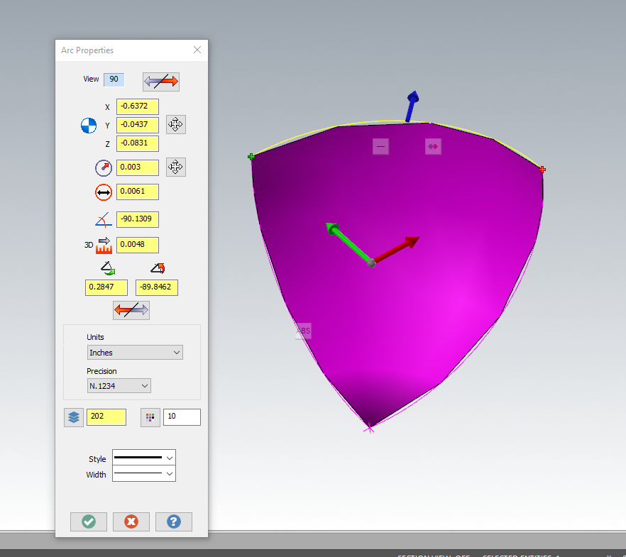
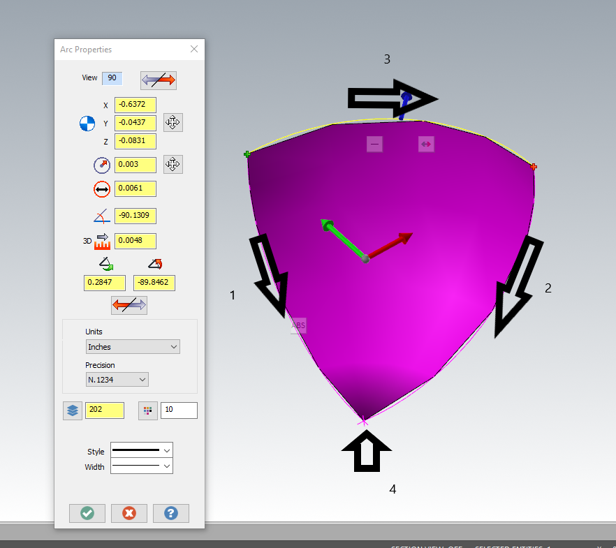
.003" yes, definitely a size issue....scale it up 50 times...make your surface, then scale it back down to make a Coons, the selection order

 5 points
 -
You can record a keystroke macro and trigger it from a keyboard shortcut or custom mouse button. I have an mmo mouse I use for things like this. I think some non mmo still have the ability to do this as long as you have an extra button??
 4 points
 -
Having a single Stock Model, at the end of your process, means you single-thread the removal of stock, from start to finish. Because each subsequent operation is dependent on the removal of material from the previous operation, you're limited in the speed the operation can execute at. Jake gave three great suggestions on how to potentially solve this issue. Or, just hit regenerate, and go get a cup of coffee while you wait. If you pause the operation, you can also Right-Click and set the Processor Priority flag. I like to use "High". I've seen no difference between High and Real-Time, but High does seem to give a performance boost versus standard.4 points
-
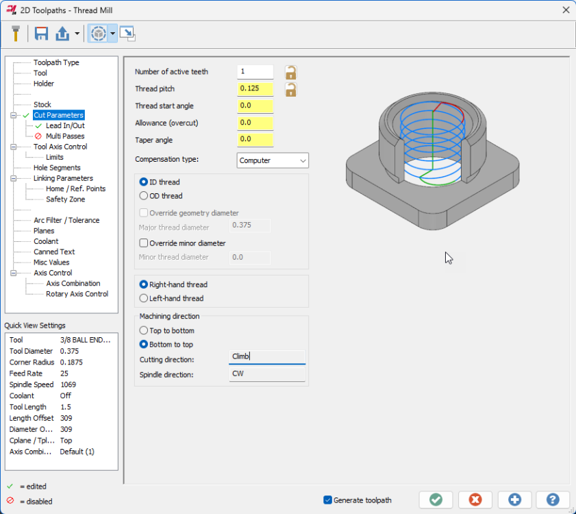
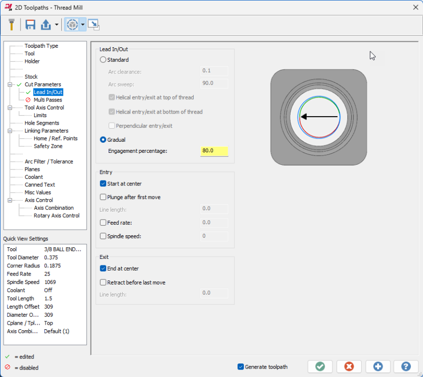
AMW, I'll pass this thread on to the product owner. Just a note that 2025 has received a bevy of Thread milling enhancements developed in concert with tooling manufacturers. Check out the Gradual entry on the lead in/out page to reduce shock load on engagement and the expanded entry/exit controls and speed/feed overrides, among others. Spindle direction is also now considered when displaying cut direction in the Machining direction box. Here's the full list of changes: Mastercam 2025 – Thread Mill Updates – myMastercam
 4 points
 -
This is one of the many areas I believe Matsuura is FAR superior to the toilet bowl lovers in machine design. Matsuura can get closer to the pallet center with the head/spindle. Doing this allows you to run shorter tool assemblies and it requires shorter work holding to get ot he part. All that to say a more rigid machining setup = the best metal removal scenario possible. In the MAM series they offer the MAM72-35V, MAM72-42V, MAM72-52V, MAM72-70V, and MAM72-100H. Then in the CUBLEX series there is a CUBLEX-35 and a CUBLEX-63. There was a CUBLEX-42 but I believe they discontinued it. 350mm, 420mm, 520mm, 700mm, and 1000mm respectively. The number after the dash is the CM value of MAX pallet Changing swing diameter essentially.4 points
-
It can be done effectively... it just has to be approached in the right manner. The #1 issue with inspecting a part on the machine that produced it isn't that the machine is checking itself, it is that the connection between the coordinate system that manufactured the part and the coordinate system that is inspecting the part isn't broken. You MUST break that connection in order to get an accurate measurement. On a 5-Axis machine with a FANUC control, that means having G68.2, G54.4, machine parameters set correctly, AND the probing software that supports probing with those functions active. Don;t have ALL those things squared away and there WILL be trouble in paradise.4 points
-
Support should be the #1 consideration when buying a 5-Axis machine. Much like a multi-tasking lathe support will make or break that machine. You could buy "the best" (whatever that is) machine but when the good for nothing AE shows up to train you, he (or she) has no clue about cutting parameters to utilize the machine to maximize it's capability, it's going to be on YOU to figure out. Oh sure, they'll tell you "... that's the CAM system's responsibility...", and it is, but only to a certain extent. When they cannot explain to you the role of point spacing, cut distance, and tolerance, and how it relates to machine performance, you ARE in for trouble.4 points
-
Took a quick look and it seemed easier to make a video than to write it all out (plus, I'm pretty much out of space to upload pictures and files!), hope that's okay:4 points
-
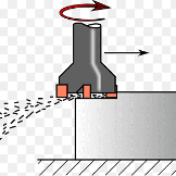
Since the spindle is cantilevered out so far, if the front of the column gets warmer than the back, or asymmetric heating of certain other members takes palce, it will arch and lift the tool much more than the linear thermal expansion rate. This problem plagues the whole UMC line, in combination with poorly done thermal comp software. To fix it with thermal comp, they would have to add a bunch more thermocouples in several locations, and have a much more complicated compensation model. What I've heard works best on these machines is to turn off the thermal comp, and take every measure you can to keep the temperature of the machine constant within a very small window. For comparison, I get less than .001" Z change over 20°F on my CM-1's.4 points
-
I'm not trying to give anyone the run around or make excuses.... I'm just trying to help some guys out on the forum using past connections if I can. I'm just a dude, playing the dude, disguised as some other dude My synopsis was just for everyone playing along at home to understand the environment. There's a lot of peeps here on the forum that I know are always curious what the actual problem is. I was trying to help everyone understand. If I didn't do a good job of that, I apologize. Collision control is all $P_WORKAREA_CS_ variables, cycle shapes just need a few special characters to open in the graphics menu. I believe this is all working fine. Syncs aren't magic either, they just aren't the same as an M-code. INIT,START,WAITM,SETM and CLEARM - took an m$, buffer and a pretty short post block to sort out. The syncs come out perfectly fine. The whole system works okay. It's just tedious because you have to manually set the syncs on each toolpath. Just like your MI$ solution (only syncs happen in the Code Expert window on an MT environment, but basically the same thing). On a "normal" machine, you don't have to to do that. After you sync, the machine will chill there until given an additional command. It appears on these machines that each operation requires a sync whether it's objectively "required" or not. That's means there's a lot of alignment PITA to manually sync everything. If you've figured out a set of rules that allows auto-syncing without manual intervention and a set of labels that can be auto applied, that's what appears to be missing from the puzzle.4 points
-
I already tried some sample code output from Camplete for Joas's YBM and got the same Z overtravel when I set the Z offset high enough. I think Colin's idea of using a regular G43 first and then turning on G43.4 afterwards might be the way to go. My new shop is like my old shop and I'm trying to run parts that barely fit into the machine.3 points
-
The only real drawback to utilizing the multi-face approach is that you'll have more tool changes. So 4 tool changes over 4 parts as opposed to amortizing 1 tool change for 4 (or however many) parts. My personal primary preference is flexibility. There is more to "cycle time" considerations than from program start to program finish. Like if the machine is running 24-7, NEVER idle, then yeah, you want that cycle time to be as short as possible. If your fully loaded machine runs for 2 shifts then sits idle for one shift, then really you gain nothing by shaving every millisecond off the cycle time because that time savings was killed by the idle 3rd shift. "There's no perfect solutions, only compromises." Thomas Sowell3 points
-
does m198 work? it works on our 0 control feeler pallet machine. we use under 500 MB cards they don't like the bigger cards I got this from james Set the machine into "MDI" Mode. Press the OFFSET/SETTING button. Change/Set the “I/O Channel” to “4” Set "Parameter Write Enable" to "1" Press the Cancel AND Reset buttons simultaneously. This will clear the alarm you get stating parameter write is enabled. Press the "SYSTEM" button. Press the numbers "138" on the key pad then "NO. SRCH" on the soft keys (below the CRT). You'll need to set bit 7 to a 1 (Bit order is as follows - 7 6 5 4 3 2 1 0 - so you'll want to change the furthermost bit to the left to a 1) Press "3404" on the key pad then "NO. SRCH" on the soft keys. Arrow over to bit 2 (3rd bit from the right) and change that to a "1" Press "6005" on the key pad then "NO. SRCH" on the soft keys. Set Bit 0 to a 1. Press "6030" on the key pad then "NO. SRCH" on the soft keys. Change it to "198". Press the OFFSET/SETTING button to get back to setting and set Parameter Write Enable to a "0". Press Reset. Now, this will allow you to run directly off your memory card. Your main program in your machine control will just need to look like the following; % O100(MAIN PROGRAM) M198P1234 M30 % Optionally, you can add a Q to the M198 Pxxxx line (M198P1234Q101) and it will jump to that line number within the Sub Program. Your program on the memory card MUST be named Oxxxx (the exes being a 4 digit number that MUST correspond to the actual Sub Program Number in the sub program. (ex. O1234) with NO file extension. Your program on the memory card must be as follows (making sure the M198 P call AND the O number AND the Sub Program Number match as I've shown) % O1234(YOUR PROGRAM NAME HERE) (YOUR PROGRAM AS NORMAL) N101 M99 % You MUST have a memory card in the slot when “M198” is called or you will get an alarm. NOTE: You’ll need to have the following on hand as well; • USB Reader/Writer for your PC so you can load programs to the Compact Flash Card. • PCMCIA to Compact Flash Card Adapter so you can load programs from the Card to the machine. • 1MB to 1GB (MAX) Compact Flash Card. The smaller the capacity, the more likely it will be compatible with your machine.3 points
-
If you look here https://www.fanucamerica.com/docs/default-source/cnc-files/brochures/function-catalog.pdf Or if it doesn't open for you - Web search "fanuc cnc functions communication software" then look at the Fanuc Brochure. Then search the 2023 Brochure for "memory" and read 098, 099, 558, 564, 774, and these tell you the latest options available for the latest controls. It looks like, for the F model, you have a 2MB maximum limit. If memory serves me, the available function is a Fanuc card that stays inserted into the PCMCIA slot with Fanuc installed software, and the control reads and processes it as "internal" memory. The best thing to do, is collate a list of your machines and control numbers, and email Fanuc explaining what you want to do, and asking what exactly you need. It seems you'll need a service visit to configure the machines to a network/DNC and at the same time they could install the extended memory and supply training for everything.3 points
-
Hahaha that's exactly what I have done. It's painfully annoying trying to even get my modifications to go as I'd like. I've thought about trying to convince the boss man to get Varco Reports. I have heard great things about it. http://varcoreporting.com/ I can see they already have feed/tooth shown
 3 points
 -
Component size....number of different part numbers to make....required geometric tolerances....tool matrix size....level of required automation....control compatibility with rest of shop....programming SW.....verification SW....etc etc.... As THEE cncAppsGuy has said, TOTAL support is #1 as you're jumping into new water with the 1st machine. Of which, successfully implemented, should lead to your 2nd machine. But it's a BIG jump from a Vert or Hori....daunting if on your own with the hot job sat waiting for you! Knowing who you can then reliably phone, will make your decision far easier IMHO.3 points
-
Ref ISO9001, there were 7xmandates when we got approval (2x man shop) back in 2007. It (9001) was updated in 2015 and the mandates were changed, but at the time I remember the assessor saying he knew of 1x UK company that was a 1x man band who had got approval and another company whose manual was 2 pages....the manual then consisted of flow downs to other documents which specified/controlled the said mandates. My manual was total of 35 pages, which was very padded out as the 1st half was design requirements and the tail end were copies of the things like CofC, Job Traveller, Invoice etc - I reckon I could have consolidated it to 15 pages if I'd removed the padding, as the design stuff was only for "sales" as we weren't "ISO approved" for that. But yes to quote Margaret Thatcher...."sometimes it is best to be specifically vague"....ie if you state ail job cards need sign off in ink, just state ink. If you state black pen, someone will use blue and you'll unnecessarily fail the audit (simplification but you get the idea). AS9100 (aero) was the next step with the only real main difference (at the time) being stock control - you had to control every inch of material, every rivet and screw and washer etc - ISO9001 you could just state (for the same material batch number) job 12345 had 10", job 12346 had 20", job 12347 had 10", of material batch number AXXXX and that was okay. AS9100 took that further by stock control monitoring so you had to detail incoming delivery of batch number AXXXX was 50", and you used 10, 20, and 10" on the 3x jobs above, so you now have 10" still left in stock (unsure of exactly how you get around tolerance of cutting and width of saw blades....for billets, washers, screws (ie "items") it's easy). Initially...."getting approval" can seem daunting, but if you break it all down to bite size chunks, the dauntingness rapidly diminishes. Certain practices you should really be doing anyway - such as material batch traceability gauge control and calibration, and office things like "contract review" which catches things like repeat purchase orders which have a revision/change, so you don't make at previous (old) issue.... Overall, it helped focus my business and got a 2x man band approved to be Tier 1x supplier for some major OEM's. Which then allowed us to grow but with control and focus.3 points
-
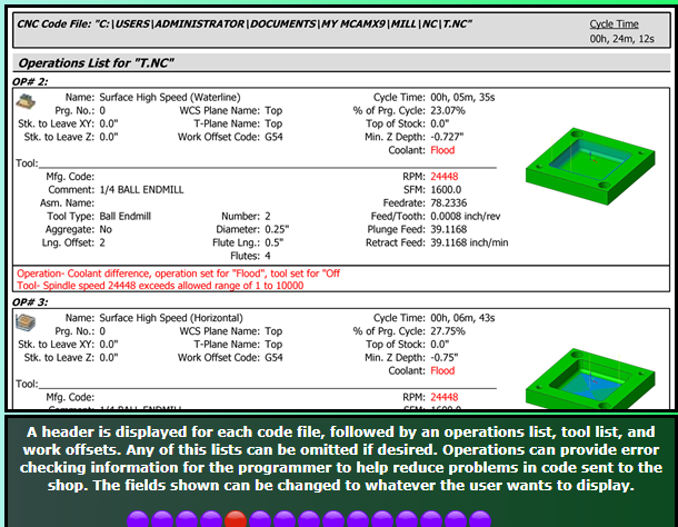
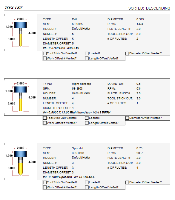
Thanks for all the replies. I ended up going with the Mill 2 setup sheet and I got a lot of fields down: Here you can see the checkboxes I added, plus SFM and RPM (thanks rgrin!). I think my main problem now is styling. That being said, I wanted to say that I do understand this a little better. When people were saying that the naming convention was important, they weren't kidding. The name in parentheses is the XML tag that the interpreter goes down to. It's almost like you're peeling back layers of an onion, except you can't really go back up, but you can dig deeper down. Another thing I'd like to say is that I still have 0 clue how to use the scripting section. If anyone has any experience with that, please advise. I think it would be a great idea to write some unofficial documentation on this so that everyone can start writing ActiveReports, because when you start to dig down deep and really learn how it works over the course of a few weeks or so, you really start to have fun making things your own and figuring stuff out. Suffice it to say, I got most of my setup sheet done thanks to this forum and thanks to everyone's help. I really appreciate it.
 3 points
 -
Ask the pushers if they want the machines making more chips or checking parts. Maybe your management team thinks differently, but my management team always wants to make more chips. Some of them may not understand much about manufacturing, but they all understand more chips = more parts = more $$ ...food for thought, a CNC can do a CMM's job but not visa versa.3 points
-
Yeah because of what I just mentioned above. When the above is done with a NIST Traceable artifact then the process is not just using the machine to inspect the part it is the process that is support the device which happens to be a CNC Machine. The device collecting the measurements doesn't matter at that point since the process to ensure what is collecting the measurements is validated and verified all is good. A CMM that is not correctly calibrated is not better than a machine tool that is not calibrated correctly either.3 points
-
Well I learned last week a major very respected builder does their machine calibration services using levels and squares not an interferometer. The issue was our programming process used was called into question. Print states one thing, but then 20 other things state 20 other things. Print is the authority unless some inspector decides no they want a +/-.0005 on a part with a +/-.010 wall thickness on the print. Or a 16 finish when the print calls out 125 and add hundreds of hours of processing time to the project. Cut 6 pockets the same exact way and 2 of the 4 are acceptable, but then as we get to longer tools the deviation between the two tools doing the work became greater. Root cause analysis looks into the root of the problem. Machine has not been calibrated in over a year. I happened to be onsite when they were going through the machine calibration and what an eye opening experience that was. Levels and squares with a spindle gauge. No external way to verify the machine is going where it is told to. This is the extent of the full volumetric machine calibration process. I called James and make sure I hadn't lost my mind and was an internal interferometer installed on the machine in question I was unaware of. NO NOT ONE HE SUPPORTS and he was unaware of one being installed either. We both agreed even it one was that at someone point would have to be calibrated. Why is this an important topic of conversation and how is it related? Here is some light reading for those that take their jobs seriously. All the hates keep on hating. Machine tool calibration: Measurement, modeling, and compensation of machine tool errors There is too much to quote that is important.3 points
-
I had the file checked and I was told was suspected pirated software used to create the file why I never responded back.3 points
-
Personally, I'm an Okuma guy. We bought an Okuma MU1000H in 2013 and have run it hard 24 hours a day 6 days a week for a decade. It has been such a good machine we bought a 2nd one in 2023. With a 170 station tool magazine and a 2 station pallet setup they are consistently the most productive machines in the plant. A 6 station pallet changer is available for these, but that would take up too much space for us. We struggled to find room for the 2nd machine. They build vertical trunnion machines as well from 4000mm tables to 8000mm. Okuma 5 axis machines3 points
-
Whether or not inspecting on the same machine that made the part will meet your needs, will depend on your needs. If you want to do it properly, you should meet the same bar as for other measurement methods; get your machine laser / ballbar calibrated, do a measurement repeatability and uncertainty test, etc., and make sure that your uncertainty is less than 1/10 your tightest tolerance. You can include measuring a gauge block / pin / ring as part of your inspection process to warn you of any calibration drift, thermal expansion issue, or other problem.3 points
-
Going to see if I can talk the boss into those Saunders Machine plates. $4800 for the three machines, bolt them on, modify the vises and done. After sleeping on it, I really don't want to bore holes in the tables.3 points
-
Ball Lock® (jergensinc.com)3 points
-
Thank you for the information, and I might reach out to you depending on the outcome of our help from Mastercam. They are currently working behind the scenes to get this problem resolved, and I am very optimistic that they will get it figured out. May not happen in a short while, but Rhome wasn't built in a day either!3 points
-
We had a Fanuc controlled VTL that was very touchy about arcs A Fanuc service tech came out and adjusted some parameters that controled the tolerance of arc endpoints and radiuses. That solved the problem3 points
-
Sorry been on the road for the last 6 weeks and still on the road the next 4 weeks and was killing a little bit of time on my 16 hours home between trips. Was trying to give you more feedback, but out of space to post up more screen shots than what I did. It was education file and as such only a few people could even open it. Like I said I don't have an older version of Mastercam on this computer so what good would have it done to post it up anyway? qc (at) mastercam (dot) com is where you are more than welcome to report the issue you have found. You came in blaming the software and its lacking and I wanted to help point you in the direction to know it was possible. Free time is funny when people try to be helpful to others thinking someone else owes them something. I helped on my own dime taking away from other things I could be doing and sorry I did it in a hurry taking care of 5 other things at the same time. Your attitude is what I suspected it was going to be when reading that first posting and like the last 21 years on this forum you have followed it to a script. Come in blaming Mastercam for its shortcoming. Get upset when someone shows you that yes it can do what was asked and when others point out that you are being an a$$hole then deflect it on to them verse being a person and admitting you came in with a axe to grind verses looking for real assistance. Was is possible? Yes it was. Was it shared in a way others can help with? No it was not, but you got answers anyway, Now your upset that yes the software can do what you want just not the way you feel it should do it and as such it is crap software because you don't like the way it does it when it can do exactly what you originally asked for was can it do it. That about sum it up? Is this a bug? How would any us know if it is a bug or not? We can theorize all day long and call things we find bugs. I do the same thing all the time calling things in Mastercam bugs, but when it could get the job done with some settings that needed to be changed does it make a bug or a user preference?3 points
-
True dat.. If it doesn't work, they shouldn't be selling it,,,, and they sure as hell shouldn't be calling it "turnkey"3 points
-
The machine support from DMG is pretty top notch, they moved some mountains when my old shop was getting through the commissioning of our CTX. App support was decent, really good with anything controller related, absolute pants with CAM/post things. Overall, I really liked that machine. The only post solution IHS was willing/able to offer was an M/T environment that would post bare bones ISO. No Cycles (rough turning, threading, etc.), just good old line by line, "re-post if you need to change something at the machine". I ended up just adding a ton of modifications to MPLMASTER and made a CHOOK to generate the MPF and SPF files after being told by the post department that they couldn't do it. Hopefully there's better options available (doesn't sound like it from your post), but you guys should be all over them if the provided solution isn't coming close to expectation, it certainly wasn't provided cost free.3 points
-
Disregard..... After opening the license activation wizard and looking around, I saw the license "deactivation" option and deactivated the HLE license. Probably should have tried that before emailing my reseller or making this new topic Maybe this will help someone in the future with the same issue.2 points
-
Holy molee, I have always reacted with a Ctrl+Z, and it never works. I'll try to stop next time and pull them from the fire. Had to update my 3Dconnexion software to get it to work, it was running the keys too fast and it happened before the flyout was available. The new update added delays to macros, so I pulled it off. Thanks again for the help. Actually ALL the help your resources have been over the years, appreciate it!2 points
-
So, it is often the case that the starting position for a TCP move can gouge or completely violate the part, if you're starting a path that is "on the far side of the part", or if you're transitioning between one side of the part, to the other. With a "Dynamic Work Offset or Tilted Work Plane" pre-position move, you're essentially 1) activating a work offset, 2) rotating the table into the correct starting position, 3) calling DWO/RTDFO to "dynamically align the active rotary face (A/C or B/C table position)" to a coordinate system attached to the part, 4) moving into a safe "XY Position", 5) using G43 to preposition Z with Tool Length Offset active, so you're driving the XYZ Tool Tip Position in coordinates which relate to the feature or zero position on the part. In terms of looking at the code, using G68.2 makes it really easy to gauge position and approach/retract moves, with a WYSIWYG (what-you-see-is-what-you-get) approach. With TCP on a Table/Table setup, Ben mentioned, "X6.7 is really the Z-Axis". The XYZ Coordinates for TCP are output as if the vectors are related to the "part setup at Rotary Zero", which means just "reading the XYZ values with G43.4 active" is not as straightforward as it would first appear. The anecdotal evidence I've seen shows that "DWO/TWP Pre-Positioning" generally solves this issue, which is why it is featured as an option in most advanced Post Processors. In the ideal setup, you pre-position using DWO/TWP, position tool tip using G43 (TLO), cancel TLO with G49, then cancel DWO/TWP (G69), and then invoke G43.4 Hxx, and if you output the same XYZ starting positions (or not), then when the TCP moves start, you're already perfectly in position because of the pre-position moves, and the path essentially "always works", or at least you can catch issues and diagnose root cause, much more easily by observation during the pre-position process. On a Table/Table VMC machine, using TWP, you're essentially always rotating a plane on an angled face into alignment with the XYZ machine axes. This means in general that "Z = Z" once G68.2 is invoked, provided it is setup properly (machine parameters) and called properly (NC Code).2 points
-
Sorry if I used too many words Correct that Mastercam doesn't (to my knowledge) have a way to create an arc from two tangent lines and a single contact point. Yep, I was going off of the original problem (at the top of this reply). What I'm saying is your second reply where you added the video gave the crucial constraint, at that point you've completed the puzzle. I'm guessing you'll be able to chook it fairly easily now that you've figured out how to do it. It probably hasn't come up enough for someone at CNC to take a look at it, because how often is this scenario encountered?2 points
-
Doing it in NX I also get Ø3.01762 points
-
Here's a video showing another workaround to get the arc I want. Dropbox - Create Arc Workaround Example2 points
-
Tool-edge feed rate would be useful in just about every toolpath, I think.2 points
-
Also, if you've got the inspection stuff squared away, it's easy peasy to generate reports, csv data, etc... If you can imagine it, you can format it, and generate reports.2 points
-
There's also less handling if you can get in-machine-inspection working right, reliably, and efficiently.2 points
-
I looked into this and it looks like this escaped the What's New, but the description above is accurate. It's hard to quantify the changes you'll see other than "It does better in some scenarios". Because the results are different enough that it could change existing Swarf toolpaths substantially, they chose to leave in place the old method (legacy) as an option and default to the new Automatic in new paths.2 points
-
For 90% of people, the CIMCO add on will be way less setup pain and get you there faster, cheaper, and easier utilizing the I+ macros already set up on the machine. For 10% of the people, I haven't seen anything else on the market give the ease of use of setting up complex logic (multiple nested If/Then/Else logic) like P+ can do. Inspection+ are the macros that ship with the probe on your machine. If you use the GoProbe app on your phone (or the Renishaw manual) to enter, say, G65P9901M2.D0.5S54. to probe a .5" bore, that's Inspection+. Productivity+ was developed by Renishaw as a stand alone program (yes, you can buy just P+, not integrated into Mastercam!). The problem was they can't trust the I+ macros to be the same everywhere, that no one edited them, and that they could support all the logic they wanted so they developed the P+ macros. You'll have two sets of macros loaded onto your machine, two sets of calibration data in the parameters, etc. P+ coming out of Mastercam will ONLY use P+ macros.2 points
-
CBN Tools would also be good, but are best for finishing. They are prone to chipping. I've seen good production processes with CBN, where two tools are used, and the finisher gets swapped out to become the roughing tool, once it is worn. https://us.ns-tool.com/en/products/product_information/cbn/2 points