Glenn Bouman
-
Posts
1,498 -
Joined
-
Last visited
-
Days Won
2
Content Type
Profiles
Forums
Downloads
Store
eMastercam Wiki
Blogs
Gallery
Events
Everything posted by Glenn Bouman
-
Here is a Christmas Present for you all. In Cimco OEM just press CNTRL-W for Toolpath Statistics
-
Try C:\users\public\documents\X+\uninstX7_X+.exe
-
 Watch this video, https://www.facebook.com/video.php?v=572597186208043&theater Looks like it is a compressor screw. Can that be programmed in Mastercam or is it a special macro?
 -
Because of this issue you will also that the cycle times reported by classic backplot for drilling are much longer as it thinks that it is feeding from the clearance plane.
-
Thanks for that information Tim, that helps explain this mystery to customers and I will have to try those adjustments, when I get a chance.
-
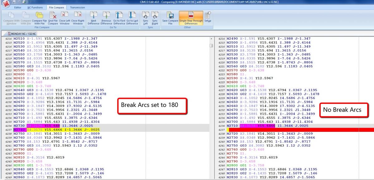
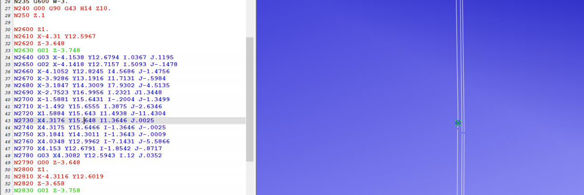
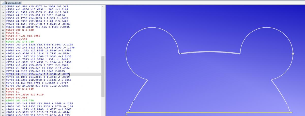
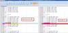
I am at a customer right now that just got bit in the !@#$%$ with this issue with a Fanuc 16i, I tried adjusting minimum arc length values and it did not make a difference. The culprit was the break arcs at 180 setting in the control definition. Since he is using IJ's, full arcs or > 180 are not a problem. The latest Cimco Edit does not show the problem, it just ignores that bad line, when I save as DXF it shows a gap. N2730 X4.3176 Y15.648 I1.3646 J.0025 N2740 X4.3175 Y15.6466 I-1.3646 J-.0025 bad line N2750 X3.1841 Y14.3011 I-1.3643 J-.0009 bad code.txt


-
I have seen this problem before on Fanucs and it always been when the customer has the arcs set to break on quadrants. Cimco Edit backplot will show the arcs correctly. You will notice that the arc segment is very short, so changing the minimum arc length to a larger value may also help.
-
Thanks for that tip Colin
-
Not anymore in X8 What are the new buttons to use?
-
I love that feature, but it is not available anymore in X8
-
Did you know Mastercam has "hidden" 5-axis toolpaths?
Glenn Bouman replied to Colin Gilchrist's topic in Industrial Forum
I find this module works manual has a lot more info in it. https://www.yousendit.com/download/elNJYUord0FTRTdFdzhUQw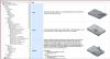
- 57 replies
-
- 1
-

-
- ModuleWorks
- 5 Axis
- (and 4 more)
-
Help with smoothing machine motion on Haas VF4-SS
Glenn Bouman replied to Pitka_Guru's topic in Industrial Forum
I checked your Arc/Filter Tolerance settings and you have the cut tolerance set looser (.09") than the filter tolerance (.0047) This will not give you effective arc filtering (I wish Mastercam would not default to this when you enable the arc filter option:( Set the cut tolerance to 30% instead of 90% and you will get better results and a smaller toolpath file. -
If it was up to me I would leave it to the lower cost janitorial staff instead of high skilled/paid folks with better things to do
-
You could set your Task bar to Auto hide to get a little more screen space.
-
MORPH BETWEEN 2 CURVES BEST TOOLPATH EVER
Glenn Bouman replied to crazy^millman's topic in Industrial Forum
I get the pictures and the animations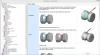
- 86 replies
-
- 1
-
-
- 5 AXIS
- PORTING LOLIPOP
- (and 1 more)
-
MORPH BETWEEN 2 CURVES BEST TOOLPATH EVER
Glenn Bouman replied to crazy^millman's topic in Industrial Forum
One of the other Moduleworks Partners has more documentation. You can get it here: https://www.yousendit.com/download/elNJYUord0FTRTdFdzhUQw -
Extending the tool depth - X7MU1 new swarf toolpath
Glenn Bouman replied to MadPickinSkills's topic in Industrial Forum
Here is a good document on the new 5 axis tools, file that I found "out there" ModuleWorks_-_Documentation.chm https://www.yousendit.com/download/elNJYUord0FTRTdFdzhUQw -
I found this explanation from the ModuleWorks_-_Documentation.chm file that I found "out there" https://www.yousendit.com/download/elNJYUord0FTRTdFdzhUQw SWARF (Side Wall Axial Relief Feed) machining, or also called 'flank milling', is a 5 axis simultaneous milling process.
-
Is this the same company? http://www.fifthaxis...-axis-vise.html I was just setting up a customer with a Haas UMC 750 (inhousesolutions post and machine simulation) with that vise, works great
-
Regardless how you explain it, making the number bigger will let it into get more areas and make it smaller if you do not want to cut those nearly flat areas. As shown in this example. BI-TAN-ANGLE.MCX-7

-
I have seen this on a brand new model and on a 1998 model. On a horizontal Haas the problem occurs in the XY plane, maybe the counter balance is not calibrated correctly.
-
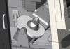
I would suggest not outputting arcs in the XZ or YZ plane with a Haas. See the results below.
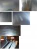
-
Good job, nice looking part, is there a way to apply a side tilt with the new swarf so when stepping down the blade the entire length of the tool does not contact the blade?
-
http://general.ca/products/6_cnc/40-913.html
-
If you have your nethasp.ini modified (other than default) Just copy it C:\Program Files\mcamx7\nethasp.ini to the cimco edit folder C:\Program Files\mcamx7\common\Editors\CIMCOEdit6