


Aaron Eberhard
-
Posts
1,417 -
Joined
-
Last visited
-
Days Won
104
Content Type
Profiles
Forums
Downloads
Store
eMastercam Wiki
Blogs
Gallery
Events
Everything posted by Aaron Eberhard
-
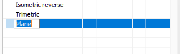
If it helps your sanity at all, I did confirm on my system that right click > rename immediately lets me type in the name: I tried it in 2019 and 2020 and works for me
-

Cutter Comp Beginning on Arc Move - How to Avoid?
Aaron Eberhard replied to Bill H's topic in Industrial Forum
Yeah, as other have mentioned, that's called the Binary NCI which is what I prefer to work in for my line of work The BNCI is pure code that comes from the toolpath, so it's as machine agnostic as you're going to get. ASCII NCI (what you get if you hit the "post" button and tell it to output NCI) is flavored based on what your machine settings are. Posted code is just the ANCI being formatted formally by your post processor. So for your sample code above, use the ultra-secret (documented in the MP post editing manual, I believe) CTRL+SHIFT+Right Click on the operation, you can choose "Display Binary NCI" (I prefer without line numbers, but you do you), and see if that call is being output on an arc. If it's not in the BNCI, then your post is adding it to the ANCI for you for some reason. -
Cutter Comp Beginning on Arc Move - How to Avoid?
Aaron Eberhard replied to Bill H's topic in Industrial Forum
Hmm, that's odd.. You should have no cutter comp at all until the finish pass? I just created a Ø.5" circle with a Ø.125" cutter, wear comp and roughing is turned on: When you look at the code that's created: G1002 0 100 10 1 1 1 0 2000 10. 0 0.87876113 0.26475797 0.5 10. 10. 10. 0 0. G0 0 0.87876113 0.26475797 0.5 -2. 0 G0 0 0.87876113 0.26475797 0.1 -2. 0 G-96 G-11 START DISPLAY TYPE - Entry G3 0 0 0.87876113 0.26475797 0.98562949 0.29990628 0.06295512 10. 3000 1 G3 0 0 0.87876113 0.26475797 0.98562949 0.29990628 0.02591025 10. 0 1 G3 0 0 1.09249785 0.33505458 0.98562949 0.29990628 0.00738781 10. 0 0 G3 0 0 0.98562947 0.41240628 0.98562949 0.29990628 0. 10. 0 0 G-12 END DISPLAY TYPE - Entry G3 0 0 0.98562947 0.41240628 0.98562949 0.29990628 0. 10. 0 1 G-11 START DISPLAY TYPE - Trans G3 0 0 0.98562951 0.18115628 0.98562949 0.29678128 0. 10. 0 0 G3 0 0 0.98562949 0.42490628 0.98562949 0.30303128 0. 10. 0 0 G-12 END DISPLAY TYPE - Trans G3 0 0 0.98562949 0.17490628 0.98562949 0.29990628 0. 10. 0 0 G3 0 0 0.98562949 0.42490628 0.98562949 0.29990628 0. 10. 0 0 G-11 START DISPLAY TYPE - Exit G3 0 0 0.92312949 0.36240628 0.98562949 0.36240628 0. 10. 200 0 G-12 END DISPLAY TYPE - Exit G-11 START DISPLAY TYPE - Trans G1 0 0.98562949 0.29990628 0. 10. 0 G-96 G1 0 0.98562949 0.36240628 0. 10. 2000 G1 41 1.17312949 0.36240628 0. 10. 0 <------- Cutter Comp starts with "41" > G-12 END DISPLAY TYPE - Trans G-11 START DISPLAY TYPE - Entry G3 0 0 0.98562949 0.54990628 0.98562949 0.36240628 0. 10. 1000 0 G-12 END DISPLAY TYPE - Entry G3 0 0 0.98562949 0.54990628 0.98562949 0.29990628 0. 10. 100 1 G-11 START DISPLAY TYPE - Exit G3 0 0 0.79812949 0.36240628 0.98562949 0.36240628 0. 10. 0 0 G1 140 0.98562949 0.36240628 0. 10. 0 <------- Cutter Comp end with "140" > G1004 G-12 END DISPLAY TYPE - Exit G-11 START DISPLAY TYPE - Trans G1 0 0.98562949 0.29990628 0. 10. 200 G-12 END DISPLAY TYPE - Trans G0 0 0.98562949 0.29990628 0.5 -2. 0 G-3 EOS - end of nci section You can see that the arcs helixing down don't have cutter comp on the raw generated passes, it's only on for the last pass. You should probably post an example file.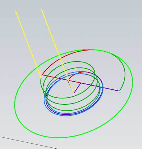
-
Tools for fixing old corrupted MCX files?
Aaron Eberhard replied to SlaveCam's topic in Industrial Forum
Good call on this, G. I forget what version (x7?) that every chain selection started remembering your chaining settings. That was a nice improvement. -
Also check out the Tool Axis Control page on Thread Mill and Helix Bore
-
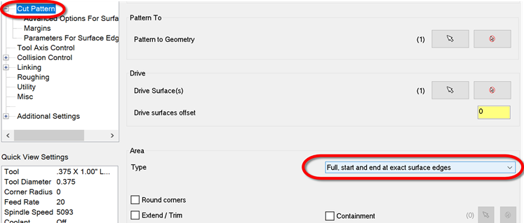
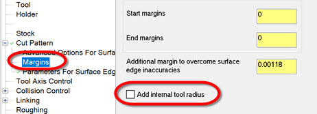
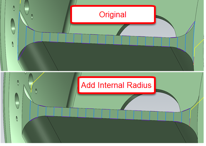
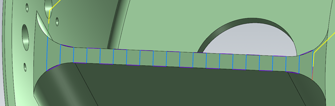
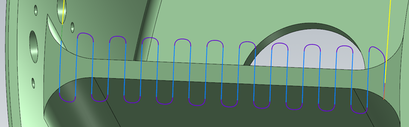
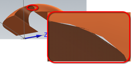
This one is easy with Morph once you know the "trick," which lies here: The toolpath as uploaded is set this way, which is cool because it gives you access to the Margins page like Mayday said. Turn this on: Now your toolpath will look like this: On a part like this, I can't see any reason to create any geometry at all. Working directly off the solid, I got this: Looks the same? Add in a bit of Cut Pattern > Extend and a Linking set to Blend, and now it looks like this: All without creating a single bit of geometry. Hope this helps!
-
Threadmill Operation Bug? WIerd quirk
Aaron Eberhard replied to Metallic's topic in Industrial Forum
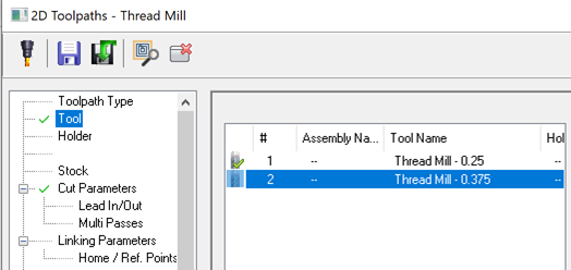
Sorry, I just re-read this, and I don't think it's the same thing that was discussed previously. Can you send a file into QC including which version you're experiencing this in? I can't replicate your behavior from scratch. I tried in 2019 & 20. Here's how I did it. I set up a Threadmill op on a Ø.500" circle, and defined a Ø.25" 24 TPI single point thread mill. I then copy/pasted the toolpath, edited the tool to increase diameter to .375" and the tool number to 2, while still leaving a 24 TPI and 1/24th as the flute length: No matter what I do, my cut parameters don't update: What did I do wrong?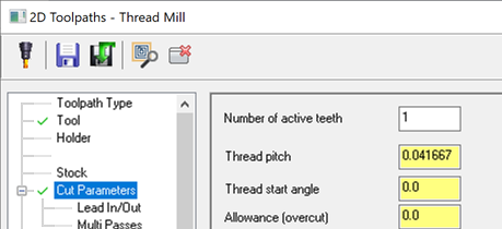
-
Threadmill Operation Bug? WIerd quirk
Aaron Eberhard replied to Metallic's topic in Industrial Forum
Hello Metallic, We discussed this back in February @ -
selecting multiple holes of the same diameter
Aaron Eberhard replied to pip's topic in Industrial Forum
If you're working directly off the solid, there's not a lot of options that make it easier in 2018, unfortunately. If you have access to Multiaxis Drill, then you can select "features" (solid holes). Hold down the CTRL key when you click to get all matching diameters. The easy button here is to use 2020 If that's possible to install the beta, give it a test drive. All hole making toolpaths use a new interface and you can just CTRL+Click to get all matching diameters, or CTRL+SHIFT+Click to get all matching diameters on the same vector as your selection. If that's either of those aren't an option, your best bet is to use Model Prep > Hole Axis. CTRL+Click on the solid to select all matching radii. Then, turn off the Points, Lines and only leave the Circles at the Top for Hole Axis. That'll give you a bunch of arcs at the top of your holes. Now, when you're in Drill, you can use Mask on Arc to select only matching radii. -
Just saw this.. We have this in the system as D-35180, it was just reported to us a few months ago, surprisingly. It affects all versions with the panel interface (2018, 19, 20). It's on the list
-
We use those (or one of the similar part numbers) here with good results.
-
cannot get morph between 2 curves to undercut help!
Aaron Eberhard replied to lowcountrycamo's topic in Industrial Forum
That option can be valid even with a lollipop tool. In this case, what you really want to do is check the shoulder (and shank?) of the tool, so that the collision control is aware of the real tool shape and isn't gouging the shoulder into the part. It will then extend only the last part (shank) to infinity. You may also want to "move tool away" "Along surface normal" instead of just trimming if there's a collision. -
You're welcome. To reverse it, on the Cut Pattern page look for "Flip cut order" under "Sorting."
-
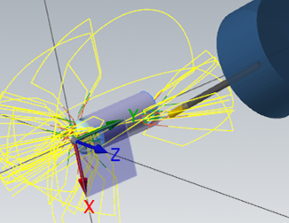
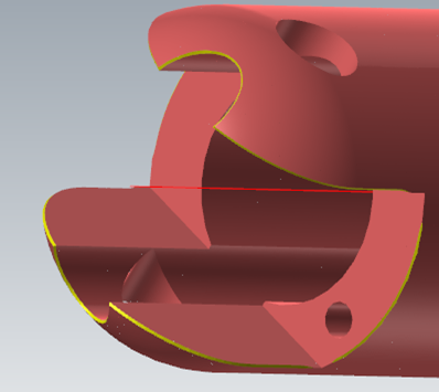
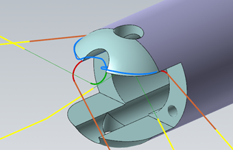
Heyo Spotterhphc, I took a quick look at this because it seemed like it would be more fun than doing real work I modified op #7, your Parallel toolpath. Stock - Use Stock Model #1 (Op #3) Cut Pattern - I hooked it up to the level 4000 geometry and set it to be Parallel to Angle so I got a constant step down. Tool Axis Control - Fixed Angle To Axis, "X." This will make it a "3 axis" toolpath, i.e., it will make the tool axis control independent from the geometry. Collision Control - CC#1 - Tilt Tool Automatically against the drive surface and the check surface (the flat bottom floor). This will cause the tool to tilt if you're going to hit the drive surfaces, modifying what we set in Tool Axis Control. Roughing - Multipasses turned on. I did 6 passes @ .1 depth, but of course you can use whatever you need here. The idea is to make sure there's enough passes that the excess can be trimmed off by stock. Multipasses will offset from the surface, Depth Cuts would have offset along the tool vector. I didn't play with Linking, but I would probably put a lead in/out on so you don't just plunge directly into the material anywhere it's trimmed. That gives me this as an output: Hope this helps! MULTI-UNDERCUT_-_ACE.mcam
-
Cool, I hope it helps you out
-
Yeah, it's the classic "I want it to be smart enough to look at the tool!" "I don't want it to look at the tool anymore!" dichotomy that we always seem to run into. In ideal-land, we would always be able to instance darn near everything from the tool & material information. In reality-land, there's plenty of places where you want to override it. The problem that we have in an instance like this is we can detect if you've changed it and never change it again, but what happens when you select a completely different tool. Would you have wanted it to update in that case? Yeah, probably. What about in the case where you've saved it with a value, but you're importing the toolpath and re-selecting geometry and tool? Etc., etc., etc.. So to be predictable, if you reinitialize the tool at all (re-selecting it, changing parameters, etc.), then update the settings. It's one of those fun no-win scenarios
-
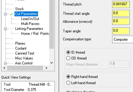
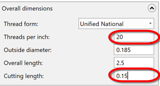
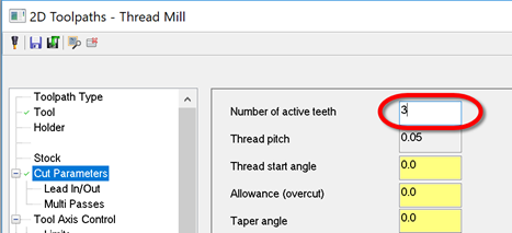
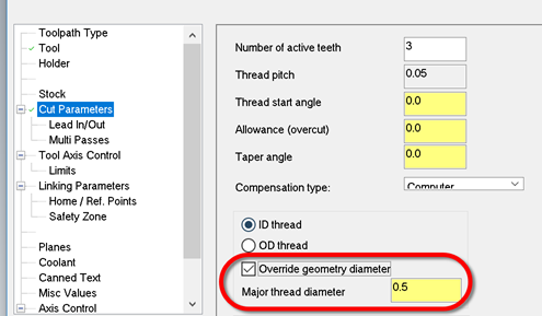
Yes, this is what it's supposed to be doing. The cut pattern page reads the tool data to determine how many threads are active, which is defined by the thread pitch and cut depth: = If you change tools or even click on your tool again, it will reinitialize that Cut Parameter page setting. If you never take advantage of using a multi-point threadmill, I would suggest that you define your tool with the cutting length set to one tooth (in my example above, that would be .05 or 1/20). Check out 2020 then:
-
Yep, as Old_Bear mentions, your standalone Mastercam license allows you to install and run MCfSW as well. Well, assuming that you're using 2017 and up (I think that's when the change was? Time is blurry thing..). You might as well take it for a test drive since you already own it!
-
Lookin' great, Husker!
-
You may want to look into "change recognition" if you haven't before, Metallic. Obviously, there's limitations if the changes are too great, but it will often work very well if all of the solid faces still retain their original IDs and such.
-
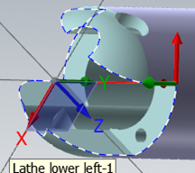
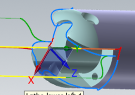
I took a look at this file, and I don't think you're going to have success the way you've defined the faces and such. The way this toolpath works is to figure out a sharp edge from what you give it. Unfortunately, with just these two faces, there's more questions than answers Think of this as if you had made a model with just those two surfaces (create surfaces from solid, for example). This is what you're feeding the algorithm: Eww. A better way to go about it is to just select the entire model. I wasn't sure which toolpath you were dealing with, so I just chose the last one, #20. I unselected your two faces and just selected the whole model which gave me this: It looked like you were really just trying to trace the slot edges, so I chose those as my "User defined" edges: I also set it to 3 axis, because I believe that's what you were gunning for? As a side note, there were lots of improvements to Deburr in 2019 Update 3, so I'd encourage you to use that if it's available. There were heaps more in 2020, so that'll be the choice once it's in public beta. Here's 2020, all I did was open the file and regen Op #20: Hope this helps! sleeve2 - update.emcam
-
Since X9 all of the 5 axis paths have worked in WCS. That doesn't mean that there's not a defect here or there, though If I recall for this particular part, we got bit by some changes made to the planes sub-system early in 2019. A lot of the stuff we build on the toolpath side relies on referencing planes, of course. We just didn't have this particular test in our automated test suite (a flow 5 axis in a non-top WCS with tilt set to lines) so we didn't catch it. We have it in there now, though!
-
2020 at this point. It missed the boat for 2019.
-
This sounds like a defect recently reported to us (R-17720) that we just fixed.
-
multiaxis toolpaths locked to 3 axis on HMC?
Aaron Eberhard replied to motor-vater's topic in Industrial Forum
In general, Parallel will often give a better toolpath than Triangular Mesh, just based on the underlying technology. The equivalent of "constant Z" is to use Parallel set to "Angle" (as in, "the path will be parallel this angle"). Of course, you can always convert it into a spiral instead of an actual constant z, water-line style toolpath just like you can with Triangular Mesh.

