AHarrison1
-
Posts
580 -
Joined
-
Last visited
-
Days Won
7
Content Type
Profiles
Forums
Downloads
Store
eMastercam Wiki
Blogs
Gallery
Events
Everything posted by AHarrison1
-
I guess there is no reason really, apart from individual preference. For instance when converting imperial to metric or vise versa i use 25.4 as my conversion factor. My manager uses 0.03937, different factors and opposite multiply/divide but same result.
-
Way back in the day effective thread depth was 1-1/2 x thread diameter which the above equates to plus a little less than one turn.
-
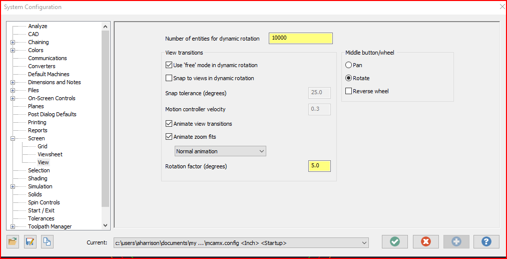
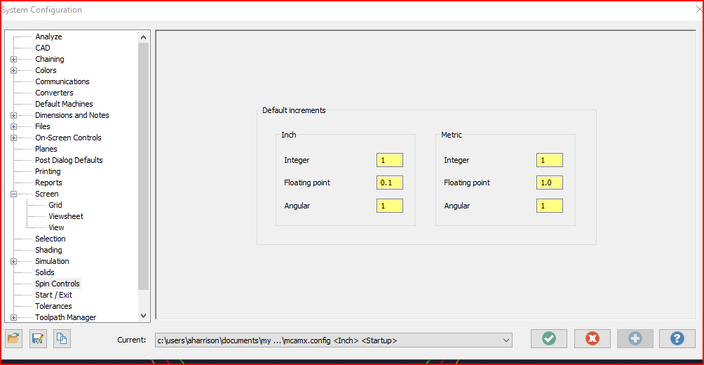
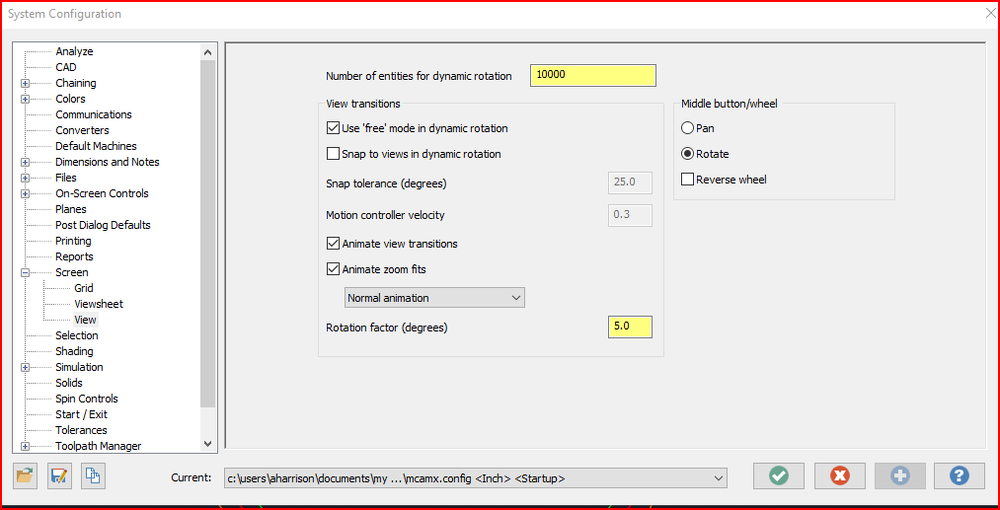
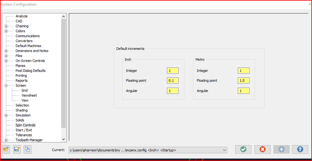
These are my settings if it helps.
-
There are a variety of options, below links are just an example after googling back spot facing tool https://mollart.com/tooling/black-spot-facing https://www.erixtool.com/front-back-spotfacing
-
I would suggest backing up Your 'My mastercam' folder in documents and 'Shared mastercam' in public documents. Once you have re0installed Mastercam copy and replace these 2 folders and everything should be good as far as settings, machine def and tool libraries are concerned.
-

Reducing the amount of G code on Thread Mill operations?
AHarrison1 replied to [email protected]'s topic in Industrial Forum
What does the code look like? G02/G03 or a whole bunch of G01? If G01 then un-check this.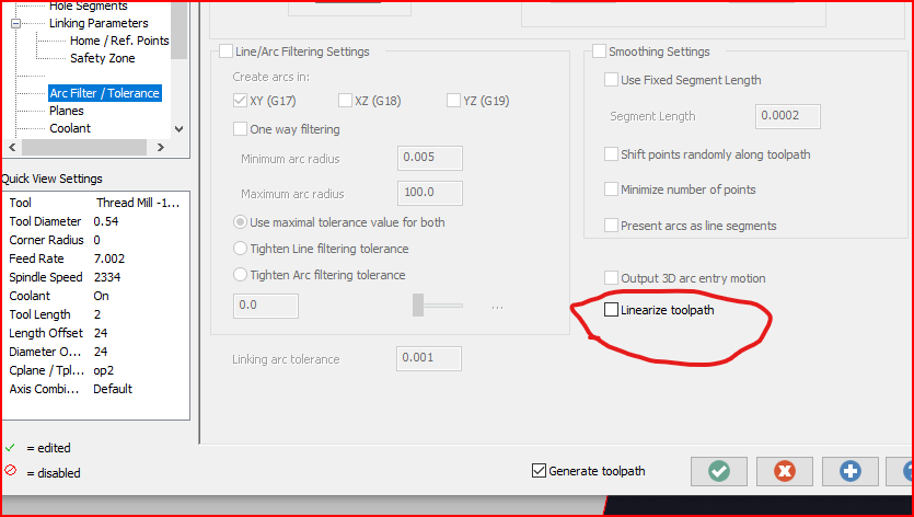
-
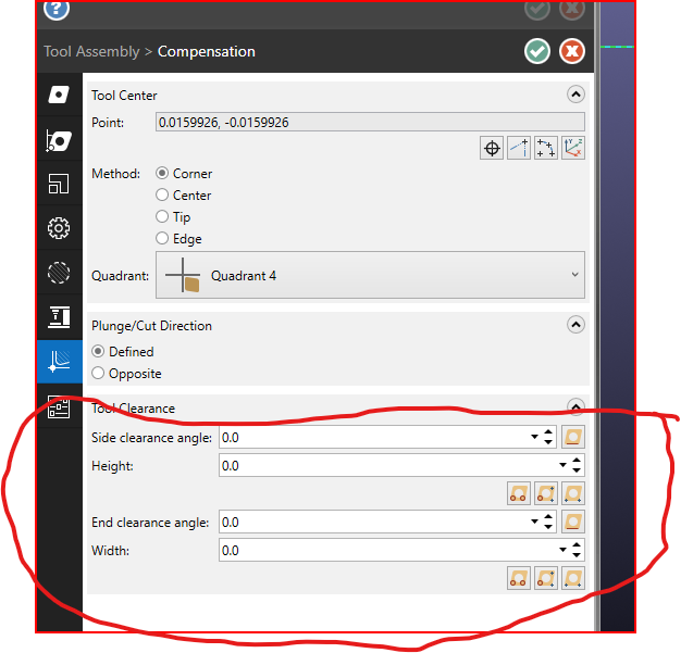
You need to finish defining the tool clearance. There is no tool width.
-
LOL... Happens to the best of us.
-
M14 activates the main spindle break, I say main as I have a duel spindle lathe here.
-
Have A look here

-
Does the migration wizard not do this for you? I have yet to have any issues migrating workspace files / right mouse settings.
-
Need Help. May be a windows problem???
AHarrison1 replied to metalmansteve's topic in Industrial Forum
Are you using 'One Drive'? -
Have a look at Mastercam 2021 Tool Designer Tutorial found here https://my.mastercam.com/learning/tutorials/mastercam/ Once page is loaded use the dropdown to select the 2021 release. I think Chapter 6 or 7 (2nd to last) of this tutorial covers multi insert tools
-
CNC programmer salary? and my Work life story
AHarrison1 replied to [email protected]'s topic in Industrial Forum
When I was an apprentice, some 30 years ago now, my foreman at the time said pretty much the same thing. His was " After 4 or 5 years in a company if you haven't moved up then you have to move on" -
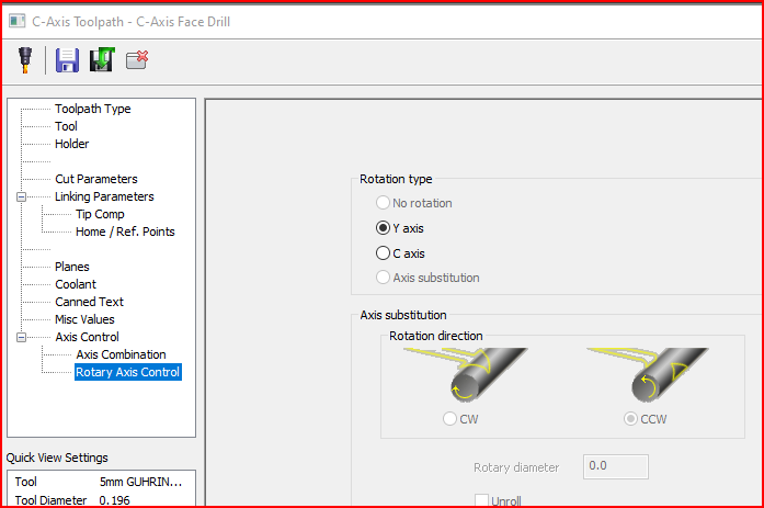
Is this on a lathe? In Toolpath parameters at the bottom is Rotary Axis Control, select Y axis
-
Good to hear... the understanding bit at least..:)
-
Sounds like you are going to have to do some trial and error with A test block.
-
The latter, Mastercam will have the tool Diameter. Your posted code would then have work piece dimsion plus half the cutter diameter. Does the offset column effect tool diameter or length?
-
In the tool offset page of the control there should be columns for dia wear offset and length wear offset. When using wear control in Mastercam then there should be zero tool diameter set in control. When adjusting for wear offset to remove more material a minus wear is entered into the wear offset for that tool. So in your case you are measuring .751 then -.001(diametric) in entered into wear offset (This is on A HAAS control) I don't know if the wear offset on your machine is set radially or diametrically.
-
I would consider making some of the machines material specific. You can then load up the tool carousel with the material specific tools. Stack the carousel with common tools. If you recycle chips i.e. aluminum then chip management becomes streamlined.
-
Once the plane has been created you can then move the new plane to the part center line. As long as the Y axis passes through the center of the hole you want to machine. The c-axis will then oreint the hole to 'C 0" (could read as 45 deg or whatever). Then there is very minimal movement in the Y axis when machining these holes. We have A DS30y here and this is how I handle features like this.
-
I would consider making planes for each hole with either x or y axis passing through the center of each hole, origin is still center of part. The planes you created should then index the c-axis so that the hole center lies on the x-plane. You can then program each hole using x and y to helix the hole.
-
Check in your control Def
-
The G95 at the beginning of that line is Feed per revolution mode as per https://www.helmancnc.com/okuma-mill-g-and-m-codes/
-
No one knew... for 21 years nobody knew.