AHarrison1
-
Posts
580 -
Joined
-
Last visited
-
Days Won
7
Content Type
Profiles
Forums
Downloads
Store
eMastercam Wiki
Blogs
Gallery
Events
Everything posted by AHarrison1
-
A few things before diving to deep. In your tool definition, increase the Cutting length to include the top rad. I bumped it up to .125". In optirough cut Parameters the 100% stepdown = 1x tool diameter. Change this to manufacturer recommendations for depth of cut, The Step over distance can be bumped up to 70 to 80 %
-
For those using 2024, update 1 is available. Upon launch a pop up appears informing you of just that.
-
Must be a typo, what with the 'A' and 'I' keys being so close together.
-
This x 1000, would also be applicable to 99% of threads where people want something specific added or removed from the software.
-
Lathe G71 retracting at angle
AHarrison1 replied to Tinger's topic in Machining, Tools, Cutting & Probing
My apologies, I made the assumption that this was Mastercam related. -
Lathe G71 retracting at angle
AHarrison1 replied to Tinger's topic in Machining, Tools, Cutting & Probing
Check Control Definition - Linear - Lathe - Rapid Motion check 1st option 'Each axis moves at maximum feed rate independently'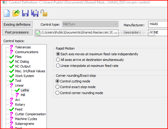
-
A place I used to work at actually did away with paper set up sheets and used Ipads for all shop floor communications. This was done with software called Mr.Narrative https://www.invawarecorp.com/mrnarrative. The concept was every part was called a book The Chapters within the 'book' was broken up into departments. There would be a chapter for engineering, a chapter for quality, chapter for machine shop setup etc. Within each chapter would be pages, for e.g In Quality chapter would be a page for quality alerts, a page with links to machine specs and a page for inspection data. All updates were live so as soon as an entry was made to say Quality then that change would become an alert for that part. For tool setups, each page would be a different tool with pictures that could be taken and added with the Ipad.
-
Depends on what control you are using. On our HAAS G99 commands Feed Per Revolution. This ties in with spindle RPM commanded by S (S1000) and M03 This does not work if we are using live tooling as the RPM is commanded by a P (P1000) and a different M to turn on the Live Tooling.
-
Two threads asking the same thing??
-
Are you using Mastercam at all or writing the code out by hand? To answer your question, yes you will probably have to modify N110 as well.
-
The X difference in N86 and N108 is .015, this should be the same difference in N85 and N107. Try change N107 to x 3.8238
-
To add to what Jake said, There is not enough room for the arc move to complete. N85 and N107 are the same values but the following G3 lines have different X values so the math does not work out to complete the arc 2nd time around. @ N107 add .015 to the x value (difference in X values in following G3 lines)
-
See here https://www.haascnc.com/service/alarm-search.alarm=ngc_304-0000.html From above link: Alarm Search Results: 304 INVALID I, J, OR K IN G02 OR G03 The center point of the arc is incorrectly defined. Possible causes are: 1) Incorrectly defined I, J, or K values. The I, J, and K values define the distance and direction in X, Y, and Z from the start point of an arc to the center. Make sure that the values are signed correctly (+/-). 2) Incorrect plane selection. Make sure that the active plane is correct. Only the I, J, or K values specific to the selected plane are allowed (G17 uses I/J, G18 uses I/K, and G19 uses J/K). 3) Incorrectly defined arc end points. Make sure that the end points for the start and end of the arc are programmed correctly. In this example, point 1 is the start point and point 2 is the end point of the arc. The J-value is negative (-) because the distance along the Y Axis from the start point to center is negative. The I-value is positive (+) because the distance along the X Axis from the start point to center is positive.
-
I think you will have to back to 2017 or 2018 to migrate from X9. It's something I have had to do before, re-loading older versions to migrate up.
-
Collision Detection Options won’t “save” – Mastercam 2023
AHarrison1 replied to M Ham's topic in Industrial Forum
You have 2 options here; 1 - in simulator goto File - Defaults - Save to Defaults 2 - Click on the dropdown tab and click on save to defaults to add to the QAT and then save,
-
Well... there are some here who will tell you to run for the hills, there are others who will say 'Meh' I would suggest youtube to see if things make sense to you. Create an account at https://www.mastercam.com/ and download the demo/educational version and start venturing down some rabbit holes. https://learningedition.mastercam.com/
-
Stock setup page 2023 how to select diplay/shaded
AHarrison1 replied to Programinator's topic in Industrial Forum
Check on the ribbon bar, under toolpaths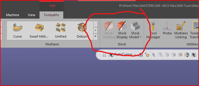
-
...totally perplexed and lost by the looks of things..
-
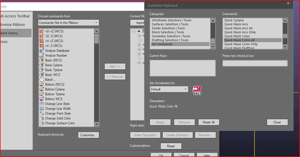
Mastercam keyboard shortcut for selecting color
AHarrison1 replied to XXDALIXX's topic in Educational Forum
Go to - File - Options - Context Menu - Keyboard shortcuts - Customize. Under Categories scroll down to All Commands (left column), Under Commands scroll down to Quick Mask (Right column) Assign keyboard shortcut
-
Stepover used in dynamic milling
AHarrison1 replied to Harshad's topic in Machining, Tools, Cutting & Probing
This will be very much dependent on tool manufacturers recommendations. -
... makes you wander if Myanmar or Liberia were even considered for naming of unit type
-
How do you download the latest public beta?
AHarrison1 replied to volitan71's topic in Industrial Forum
It is available under the Mastercam tab (1 below 'Latest release') but , as you said, no formal release has been announced. -
I'm guessing it's the same functions as the buttons below

-
3 icons for you too then i suppose.
-
...Just not for lathe language