Leaderboard


Popular Content
Showing content with the highest reputation on 04/29/2022 in all areas
-
Building skills, manual dexterity. I had a guy retire here after nearly 40 years, most skilled guy I ever met. He never used a computer, calculator etc. All designs and drawings done on paper. Everything fully shaded (cross sections with hatches) etc. He had hands like a jeweler. He would drill holes down to 0.005" (HSS drills) by hand. His work in general was pristine. Not all jobs are done on CNC equipment in my field.3 points
-
Sorry, I just saw this. I'm not visiting that much now since we are swamped getting ready for IMTS. Cruzila, I will need more info if you haven't resolved this by now. Lathe? Right? Which one and how old? What control? Send the program and show where the issue happens. I don't do turning much, enough to do with milling and 5 axis but I can ask our turning AE's. We have really good guys here in NJ and hate to see us lumped in with certain Ellison divisions, good or bad. Yeah, getting hold of Ellison is your first choice, we get the overflow or more difficult ones from them anyway. You can call us here in NJ anytime no matter. No one gets turned away. Paul3 points
-
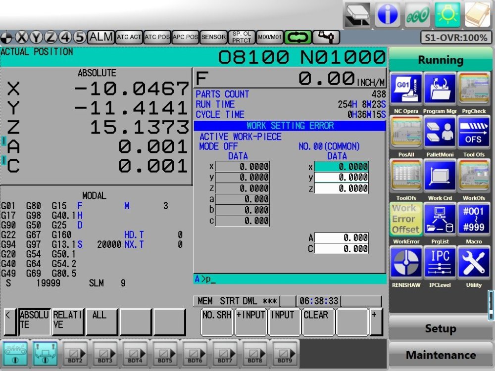
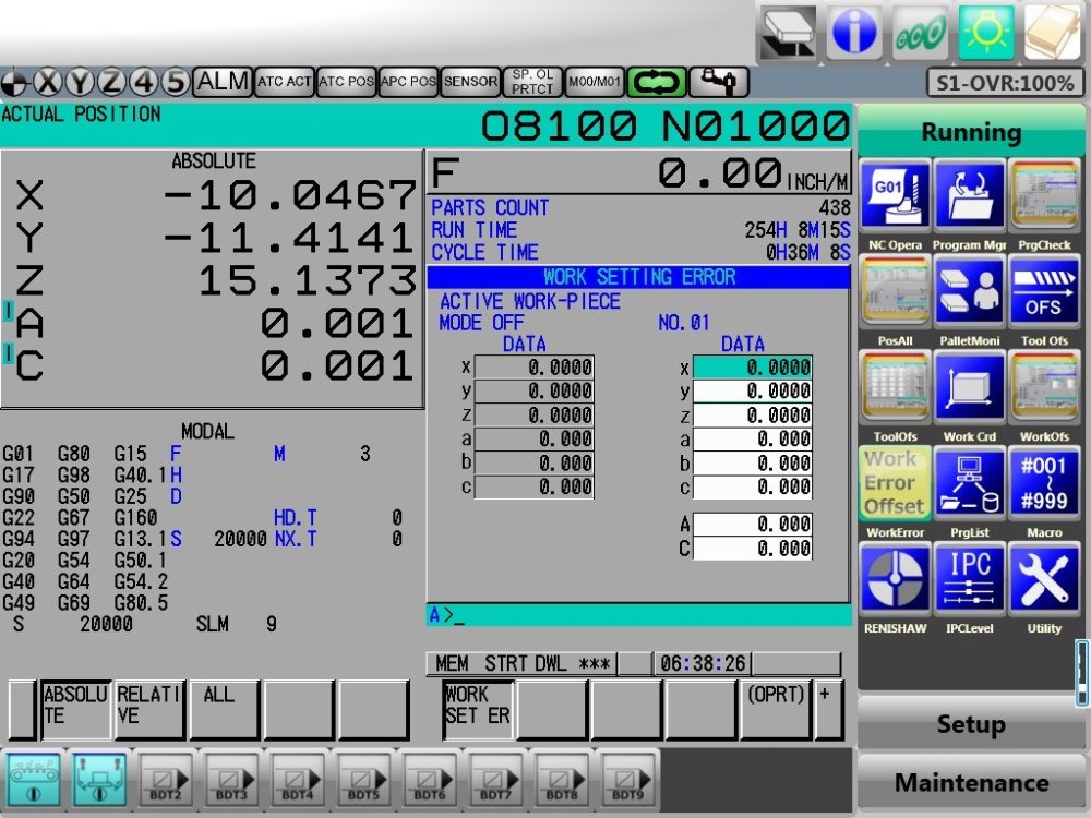
@Rstweart - The Renishaw Macros will have the G103P1 inside of the macro as you can see in my screenshot. With this being the case, whenever CIMCO Probing calls up that macro, it right away limit the look ahead and would be redundant in my opinion. Here are two examples - one is in the 9810 (Protected positioning moves) & a standard measurement cycle such as 9814 (Bore/Boss cycle). Hope this helps!
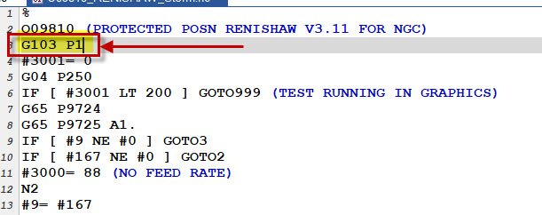
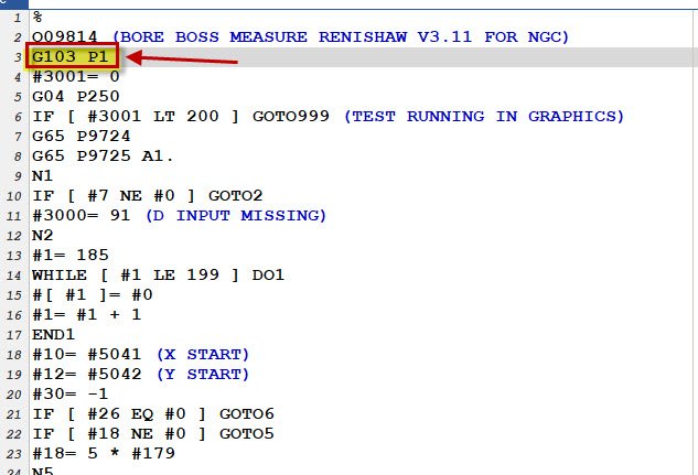 3 points
 -
that's a very easy post edit.. make the edit and call it a day2 points
-
Go into here... and select this option I think that's what you're looking for.. If you look closely, you'll see the little yellow point moves from the front, down to just above the remaning stock2 points
-
Cruzila, Your mention of threading threw me of, making me think it was a turning center. I agree with GCode. Your safety line should only contain G Codes and (M Codes?). You should not put any axis moves on that line. The DNM5700 lives in G17 and should not be needed but is not a bad idea to be redundant. You stated in the OP that moving the A Axis move to the next line lets it work. All of my showroom mills have #5109.0 set to "0". This seems like a programming issue, not a machine issue. Fanuc is a finicky beast. Drop all of the axis moves down to the next line. Paul2 points
-
When I get my computer open in about 40min, I'll see what else I can dig up. I know when you set you errors, if you don't put in the machine angles you took the measurements at, you won't get what you're after. You should have no tilt or rotary values in your work offset.2 points
-
At Dunwoody in the 90's we hand filed our first project to shape after roughing it out on the bandsaw, after welding our bandsaw blade and laying out the project with Dychem and hand scribing. I think it teaches a lot; you learn an instinctive understanding of the material properties etc., and an appreciation for the more efficient modern methods. Plus if you ever have to fall back on it, you have it.1 point
-
If I have to file something, I've failed somewhere. I mean unless I'm just filing some sawn stock so the saw burr doesn't influence my probing cycle... then yeah, I'll file or deburr. Otherwise the machine does all the work. the better a part looks the less scrutiny it gets. Don't get me wrong, I always want to make a good part, I just don't want to draw any unnecessary attention to my stuff.1 point
-
Out of curiosity, Why? Most of today's machining doesn't even require hand deburring. Hand working parts is definitely an art so don't get me wrong, but try to find someone who even want's to do it these days. If I bring a part to QC that needs to be filed in any way I would probably be reprimanded. :D1 point
-
This Helps immensely, Thanks James. Ill do some experimenting tomorrow.1 point
-
Here is a sample program from a DNM5700 that I did a 4th Axis program on. It's at the beginning of the program and the second tool change. G20 G0G17G40G49G80G90 (DRILLRIGHTSIDEJOURNAL) T1M6 G0G90G59X1.125Y0.A90.S2037M3 G43H1Z6. M7 G98G81Z1.3R2.6F24.22 G80 (DRILLLEFTSIDEJOURNAL) A270. G98G81Z1.3R2.6F24.22 G80 M09 M5 G91G28Z0. A0. M01 (ROUGHHELIXBORE1.250DIARIGHTJOURNAL) T2M6 G0G90X1.125Y0.A90.S3056M3 G43H2Z6. M8 Z2.6 G1Z2.5F25. G3X1.1992Y.0742I.0371J.0371F55.011 point
-
Yes learning is part of our job and just had this conversation with a Customer this week. I am always learning and growing my craft.1 point
-
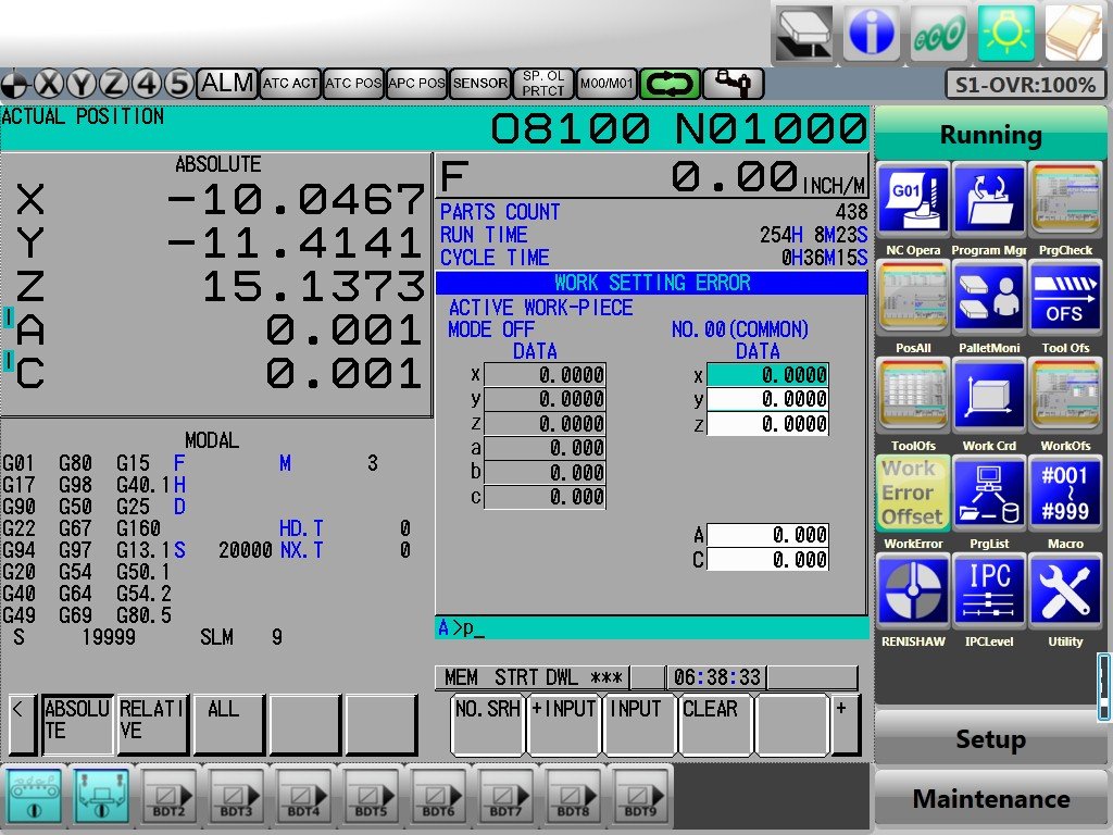
Since you (presumably) have the MAPPS interface I'm not absolutely certain of the keystrokes to navigate to the WSEC offset table on MAPPS. On a FANUC interface (Standard, Panel i, or iHMI) it is OFS/SET (Offsets/Settings), right arrow soft-key to WORK SET ER. There will be 8 total screens. The first screen is the common screen. Here you only have X, Y, Z, your Tilt Axis and your Rotary Axis (A/C, A/B, or B/C). (See below (This is Matsuura's overlay on on a FANUC 31i-B5 with iHMI Interface - the stuff around the edges is specific to Matsuura, the gray stuff is the normal FANUC stuff) The next 7 screens are your P1 through P7 G54.4 offsets. The screens are from a Matsuura MX-330. Lower case letters are your errors. Upper Case letters are where you put your Machine Tilt and Rotary position when the error was recorded. Some times you need several rotation angles to get the correct data. If that is the case, you need to leave the Tilt and Rotary angles at 0, then you need to figure out what errors go to which axis as if you were at 0, 0, 0, 0, 0. To explain all the possible scenarios this by writing would take a considerable amount of time. It's on my To-Do list to do a YouTube video to explain it... hoping soon. Hopefully this at least gets you going.
 1 point
 -
The biggest difference between silhoutte boundary and create curve on edge, or create curve slice is that sihouette is a projection type creation...it will pick up on VERY slight variances in geometry. You see that reflected in how it sometimes catches corners and even straight geometry if it shares a common edge but at several Z depths...you can try tightening up the tolerance and using Arc fit....even with those however, you might find slightly "less" than perfect geometry. I typically will not use silhouette boundary for anything beyond a roughing path.....if I need good clean geometry to cut, I'll use Create Curve edge or Create Curve slice..1 point
-
i got 12 in the last day1 point
-
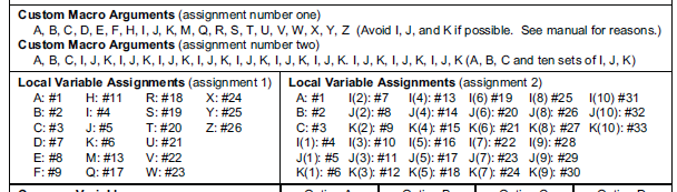
yeah depending on the #used, fanuc has Local, Common and system variables. Heidy variable example: Q temporary variable. Q1=3.84 QL local variable. Temporary variable true on in program it was issued. QL= 3.82 QR permanent variable, until overwritten. QR = 3.82 QS string parameter QS = "HELLO" then there is architecture to read string parameters as data, and functions to read and write system data.1 point
-
That's what killed this place - too many emotions and the overlords shut it down.... Pretty ironic - I just earned "top rank" (?) for December 2006. I know I'm stuck in my ways - can I return back there please?1 point
-
I'd just send the questions to your reseller. CIMCO probing, when we did testing, came with the modified haas 3/4 axis post directly from them and it was 100% plug and play. I'd be very surprised if there were suddenly any issues with posted output. If your reseller used their own post and added CIMCO probing routines, (which is not a big deal to add into a post,) then maybe there are some slight tweaks to be made.1 point
-
Haha they have it all backwards. We don't need AI to replace us lowly programmers/AE's....... We need to MERGE with it to create a race of super programmers so that our AI selves can replace all of those middle and upper management, as well as all of the workers on the floor with robots connected to our AI selves so WE ALONE control the manufacturing of the world....MUHAHAHAHHAHAHAHAHAHAHHAHA1 point
-
Free fiss. ^^^^^ This times eleventy bazillion.1 point
-
Sat in a meeting with one customer and that was his exact words as they were asking for our help. He mentioned a group that was on the cusp of making AI that could program any part for any machine. I asked him was it a certain group? He looked at me shocked I even knew they were doing it. He said yes and informed him they interviewed me about helping their product along. After 10 questions they realized that I was not going to be much help. Not because I was unwilling to help, but because the software was unable to do what I was asking in 10 questions. Simple part that was a flat plate with 4 holes it could handle that. Complex Multi Axis setup on a Tombstone or in a self centering vice forgot about it. He said well in 5 years you will not be needed and obsolete. That was 7 years ago and still doing what I do. That manager is not longer working for that company not sure where he wound up, but I am sure it somewhere that reality still has not caught up to the company.1 point
-
It is correct. And they will tell you all the extra lines are needed for Pro+ to do what it needs to do in regards to logic and re-machining. I've recently switched to the Cimco probing add-in and it was much better.
 1 point
 -
Something I see all the time is people "reusing" Tooling Component Solids in their Mastercam Files. They Import, Move, and Save those models, and then continually move/copy/rotate these models. All Solid Models (even those without "operation history"), keep track of the transformations "behind the scenes". After you import Solid Geometry into your Mastercam File, (Especially when using Merge), use the "No History" command, on all your solid bodies, after you've moved them into position. I also like to run "Optimize" on all solid geometry that I've imported into Mastercam. You'd be surprised how much "overhead data" you can eliminate by using these two functions. For Fixture Plates, Etc., I like to get rid of any extra holes/features, whenever possible. I will typically keep a "featured" model on a separate level, but then will go and "Remove Features" on models which I'm bringing into Verify or Machine Simulation. You want the "outside skin" of vises, fixtures, riser blocks, etc., but having an "internally modeled feature" just creates more computational overhead. This is probably not related to your specific issue, but removing Solid History can really help streamline your files, and get rid of computational bloat.1 point
-
To test use un-shading and will see the wireframe of the solids and change the resolution to a crazy number like .5" or 12mm and see if it crashes. If not then shade the screen and see if the crash happens if it does then there is the proof you need.1 point
-
Where's oneyankfan when you need him?0 points
-
This is the post that finally gets me to stop lurking and actually comment. As I read this, I was reminded of the time when I was an apprentice tool and die maker. The company I worked for was, on top of the apprenticeship, also sending me to tech. school for programming and mechatronics in the evening. One evening I was at school and we were working on a project, if you can call it that, where had to take a piece of 1018 square stock, and file the edge cut by the bandsaw until it was flat and square to the sides. A teacher, who wasn't even teaching this class, decided to share his expertise on filing with us. He proceeded to show the class how to "saw horse" file. I told him that my apprenticeship instructor told me that saw horse filing is an improper technique and he took me to his office which was near the machining area and actually took his engineering degree off the wall and shoved it in my face yelling at me. Saying that he graduated top of his class with honors and that he wasn't going to be disrespected by some kid he was just trying to "help out". I was so dumbfounded by the situation I didn't even know what to say, so I just turned and walked out of his office.0 points
-
I would just like to thank everyone that have made this possible. I could never have earned this badge without you. :)0 points
-
Yes then that MTB brought in a company to make that part without knowing that all that had gone down. Then one Year after the company had been working on the project did the time study get shared and the penalty associated to not making that time study. Then the cheap customer who had been allowed to prove out the project against what was going to an MTB prove out got all the facts showed about their own internal sabotage going on since it was done outside and not inside. Then the gloves come off and there was going ot be about $50k worth of tools thrown at the time since the clause was time not Cost per part to make that insane time happen. Then the end customer lost the project. Years later that is still not settled and one company is still looking to collect money on their machines that have been printing money for free the last few years and the company that programmed them is still looking for $XX,XXX money owed on the project.0 points