Leaderboard


Popular Content
Showing content with the highest reputation since 04/22/2024 in Posts
-
Lots to unpack there so without further adieu... 1) FANUC Program Transfer Tool (available https://www.fanucamerica.com/products/cnc/cnc-software/programming-simulation-software/program-transfer-tool for under $30 USD) . I use it and reccommend it HIGHLY. CF Cards MUST be 1GB or under for 30i/31i/0i-F series controls. I keep a 128MB (yes you read that right) card for older era machines. I get mine from Amazon. I like these for 1GB's https://www.amazon.com/1GB-Compact-Flash-100X-INDUSTRIAL-Pio/dp/B000ZNWOSS/ref=sr_1_2?crid=I99RBMCIPDWH&dib=eyJ2IjoiMSJ9.vy01M8EQ4MyyBDSDjeq_NuppS6M0tWgWrlcoasmKUzHjiYMoBe4U0bq62scns-U3Z0sxEMsM4q6X_kTLHXLVeZIRbO48o0Ipi--Hbq_FKm_aXz3hHfnB-91bIoKmwAUB53WTZHmRWTDJUWArvdnEuFhSkXyZiuemWcvM7BHOfMdrt8mszRDnM4pnfYkaWH1zERpJt7BhJnTVxO8zVuM1eqnIyDCY6XJQqDZxH8O15pWTx-OlI9AUfeXcdAxgw5UvrmuowILrWHeEtGMuZOhPyXp7I7NocgDEelaG2jZaAnk.d2rRem4np6HQzDANiXqa6evpgkauOin78IjLz0UNivw&dib_tag=se&keywords=1GB+CF+Cards&qid=1713845397&refinements=p_n_feature_five_browse-bin%3A673261011&rnid=673240011&s=pc&sprefix=1gb+cf+cards%2Caps%2C126&sr=1-2 It's only frustrating if the company you bought your machine from is not knowledgable. Support matters. Especially today. 2) This is NOT a FANUC issue. This is 100% on the machine tool builder. We spec our machines with 8MB of CNC Memory and 1GB of Data Server Memory. The latest machines have SSD Drives with TB's of storage and they are FANUC so... the problem isn;t with FANUC it's with your builder improperly specing a machine. Assign blame wher it belongs. 3) See #1 4) I barely graduated high school... and by barely, I mean if it weren't for woodshop and PE I woudln;t even have had a 2.0 GPA... and I have no trouble connecting machines to networks if they are equipped with either an Embedded Ethernet port or a Data Server. Been doing it since the 90's. You need better machine tool support. 5)I've not been successful partitioning CF Cards lately. Like for the last 10 years lately. Just get a 1GB CF card or smaller with a PCMCIA adapter and it'll work. Embedded Ethernet is a simple setup. EIther use DHCP or set a static IP address, set the router and DNS IP Addresses, plug it in and it works. Just to prove a point to a customer, I went out to Home Depot, bought a Wireless Extender with an ethernet port, set it up, set the control for DHCP, set the router and DNS, restarted the adapter and I was able to ping the CNC form anywher ein the shop. Once I was connected to their network, I coudl upload and download programs at will. 6) You just need better machine tool support 7) I give away my knowledge for free. It's worth plenty, but so many gave to me freely, I'll give freely until I get burned. 8 ) I will say it's easy, because it is. I'm NOTHING special. Believe me. I'm just an average at best guy. Your machine tool dealer has a high degree of incompetence, or they are withholding support from you. Either way, I'm sorry you are going through this trouble. You should not have to suffer because of your machine tool dealer is incompetent or your machine tool builder didn't adequately option their machine. I hope this helps. Put ALL your pat programs on the DATA_SV. Just use CNC Memory for custom G/M-Codes, Custom MACROs, etc...8 points
-
A bit of a shortcut in your method is that you can skip the "extend the two lines to their intersection point" when you create the circle. Just hit "i" key or AutoCursor > Intersection and choose the two lines, it'll snap to the intersection. ----------- You need 2 pieces of information to create a tangent arc. If you have those two pieces of information, you can calculate the missing 3rd, right? There's a critical piece of missing information to solving this, which is either the tangent point (on the bottom line) or the radius. Without specifying those two, there's an effectively infinite amount of possible answers. When you extend the bisecting angle lines, you're creating the restriction on the radius (1.50881301") so there's only one solution that fits the end point of the slanted line and the center point (Radius), which means you'll get a tangent point on the lower line at X0.57622467". Unfortunately, unless you have a specific reason for choosing the centerpoint you did (i.e., it's called out by the print to find the bisecting angle between these two features and create the radius centered off of that?) it's just really a random point in space that confirmation bias makes look more likely to be correct Note that Tom found the solution in solid works effectively the same way, using Constraints instead of the geometry.. If you use Mastercam's Arc Tangent > Arc One Point, you're now constraining two items: The end of the angled line and whatever tangent position is closest to that line. Mastercam will make an arc fitting with whatever radius you type into the panel. You can make a Arc Tangent > Arc Two Entities, which will do exactly what fillet would do, (in the background) it'll extend the angled line to the intersection and fit an arc of 1" (or whatever you specify). ----------- Basically, you're not asking the right question. For two lines of N angle, you can ask: What radius fits between these lines? Any of them, pretty much. What radius is a fillet? How many windows are in a house? If I give you a point and a line, what radius fits between those two? Any of 'em > the distance between the closest point to line. See above. If I give you a radius, where does that fit from this point to a tangent point on this line? THERE YOU GO! That's the right one ----------- I can't imagine that any CAD/CAM system can give you what you're asking for, as you're not giving complete information.6 points
-
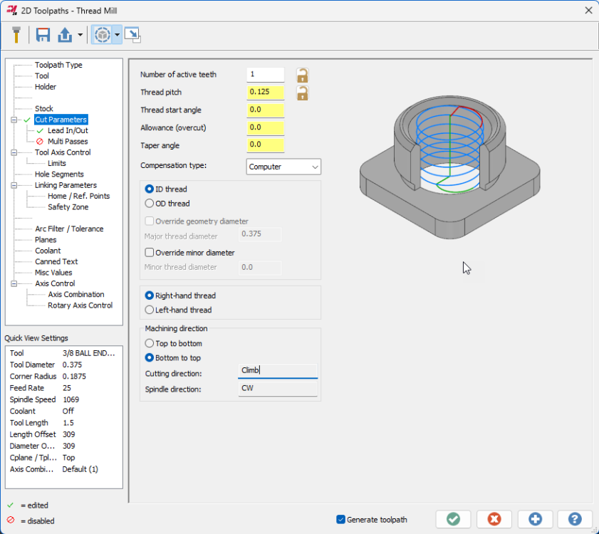
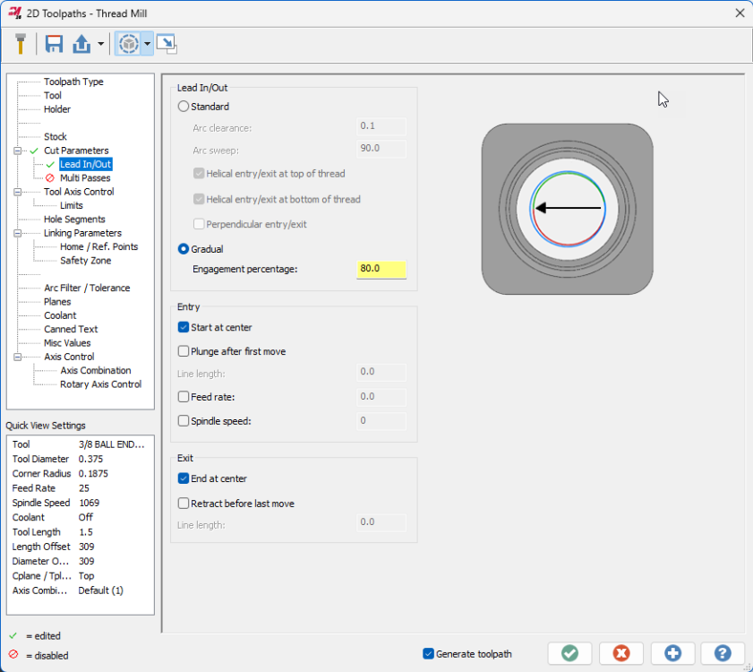
AMW, I'll pass this thread on to the product owner. Just a note that 2025 has received a bevy of Thread milling enhancements developed in concert with tooling manufacturers. Check out the Gradual entry on the lead in/out page to reduce shock load on engagement and the expanded entry/exit controls and speed/feed overrides, among others. Spindle direction is also now considered when displaying cut direction in the Machining direction box. Here's the full list of changes: Mastercam 2025 – Thread Mill Updates – myMastercam
 4 points
 -
The only real drawback to utilizing the multi-face approach is that you'll have more tool changes. So 4 tool changes over 4 parts as opposed to amortizing 1 tool change for 4 (or however many) parts. My personal primary preference is flexibility. There is more to "cycle time" considerations than from program start to program finish. Like if the machine is running 24-7, NEVER idle, then yeah, you want that cycle time to be as short as possible. If your fully loaded machine runs for 2 shifts then sits idle for one shift, then really you gain nothing by shaving every millisecond off the cycle time because that time savings was killed by the idle 3rd shift. "There's no perfect solutions, only compromises." Thomas Sowell3 points
-
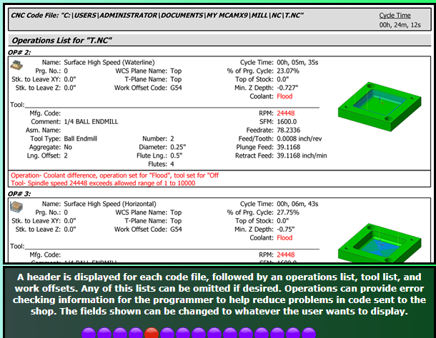
Hahaha that's exactly what I have done. It's painfully annoying trying to even get my modifications to go as I'd like. I've thought about trying to convince the boss man to get Varco Reports. I have heard great things about it. http://varcoreporting.com/ I can see they already have feed/tooth shown
 3 points
 -
We have the 1053 delimit tool path setting on as a recommendation from Camplete. What this does is on 5 axis paths since there is no transition block it zero returns z and starts the next path, no tool change spindle keeps running. It doesn't affect 3plus2 because there is an approach block short that transitions to the next path. I did mess around with the multi axis linking in Camplete but for us it's not worth using.2 points
-
I just did an undercut fillet with a T-slot cutter the other day. I used Flowline, with Direction and Depth Limits, and it worked perfectly.2 points
-
Although my toolmaking apprenticeship, turned into Modelshop/R&D, that quickly turned into the DO at the age of 21. I was REALLY fortunate that my mentor agreed to take me under his wing - he told me "I don't think I can make a silk purse out of a sows ear, but I think I can make a sows ear purse out of you" But we'd hit it off early during my apprenticeship - while work experience in the DO, he gave me my 1st job which was to copy an existing print. Mylar, 5H and 2H pencils, rule ("we don't call them rulers in here as the Queen of England has F'all to do with this job") square, protractor, compass and the most important thing eraser - and away I went. The part was the base of an instrument which was square with the 4x corners turned off, and everything was about the C/L - and I thought I was doing okay when he said "that top right quadrant - tatty - have another go at it"....so the eraser got a hammering and 15 minutes later "that's good, but it shows up the bottom right quadrant - have another go at that"....so out with the eraser again and 15 minutes later rinse and repeat for the left hand side.... End of day I remember him saying "the cleaners will love you tonight - look at all that mess on the floor" But yes, printing was my downfall - CAD was a godsend. There's 2x real arts to being a drafty from a "picture drawing " perspective - neat printing, and the most important one having the initial visibility of first laying the job out in your head so you know you can then get all views and all dimensions on the sheet. As with everything now, things change and it's a lost art - but we now have the other extreme where "everyone can use a computer", so everyone thinks they can be an "engineer"!2 points
-
Back in high school we had an old German welding/ drafting teacher, much like G-Code describes (drill Sargent/ taskmaster). He would make students cry. I still remember everything he taught us (well I think I remember!!!). Yes drafting with a T-Square and Vellum paper! I had an employee retire after nearly 40 years, he didn't use computers.... he would make "quick sketches" (his description) that were nothing short of works of art. Everything neatly scaled, shaded and sectioned and dimensioned immaculately.2 points
-
Sorry, misinterpretation on my end. You weren't finding an issue with the original question, you were providing a more in depth explanation to the provided solution. Thank you sir, this is much appreciated.2 points
-
Sorry if I used too many words Correct that Mastercam doesn't (to my knowledge) have a way to create an arc from two tangent lines and a single contact point. Yep, I was going off of the original problem (at the top of this reply). What I'm saying is your second reply where you added the video gave the crucial constraint, at that point you've completed the puzzle. I'm guessing you'll be able to chook it fairly easily now that you've figured out how to do it. It probably hasn't come up enough for someone at CNC to take a look at it, because how often is this scenario encountered?2 points
-
Went to add an edit and couldn't, but this should've gone with above post. So, OP, when you get blank pages like that it's typically because you aren't following the correct structure. It's difficult for me to make sense of the structure you have in place right now. My main sheet is (FILE), which calls (MILL-FILE), which calls (MILL-TOOLS), which calls (MILL-TOOL). Assuming you have (FILE) shown, you're then calling (FILE) and (MILL FILE) in the same report. Then one each of those calling (OPERATION) and (MILL TOOLS). I don't think that structure is agreeable. I think you need to be (FILE) - (MILL-FILE) and have that calling both (OPERATION) and (MILL TOOLS).2 points
-
Doing it in NX I also get Ø3.01762 points
-
Here you go This is a zipped Mastecam file the radius in 3.0176/2 solved Create_Arc_Sample.zip2 points
-
Here's a video showing another workaround to get the arc I want. Dropbox - Create Arc Workaround Example2 points
-
We're aware of how useful this can be elsewhere and are looking at how we can implement it. That's why we placed this edge feed rate control in the Tool page rather than sequestered away in a threadmill specific page.2 points
-
Tool-edge feed rate would be useful in just about every toolpath, I think.2 points
-
does m198 work? it works on our 0 control feeler pallet machine. we use under 500 MB cards they don't like the bigger cards I got this from james Set the machine into "MDI" Mode. Press the OFFSET/SETTING button. Change/Set the “I/O Channel” to “4” Set "Parameter Write Enable" to "1" Press the Cancel AND Reset buttons simultaneously. This will clear the alarm you get stating parameter write is enabled. Press the "SYSTEM" button. Press the numbers "138" on the key pad then "NO. SRCH" on the soft keys (below the CRT). You'll need to set bit 7 to a 1 (Bit order is as follows - 7 6 5 4 3 2 1 0 - so you'll want to change the furthermost bit to the left to a 1) Press "3404" on the key pad then "NO. SRCH" on the soft keys. Arrow over to bit 2 (3rd bit from the right) and change that to a "1" Press "6005" on the key pad then "NO. SRCH" on the soft keys. Set Bit 0 to a 1. Press "6030" on the key pad then "NO. SRCH" on the soft keys. Change it to "198". Press the OFFSET/SETTING button to get back to setting and set Parameter Write Enable to a "0". Press Reset. Now, this will allow you to run directly off your memory card. Your main program in your machine control will just need to look like the following; % O100(MAIN PROGRAM) M198P1234 M30 % Optionally, you can add a Q to the M198 Pxxxx line (M198P1234Q101) and it will jump to that line number within the Sub Program. Your program on the memory card MUST be named Oxxxx (the exes being a 4 digit number that MUST correspond to the actual Sub Program Number in the sub program. (ex. O1234) with NO file extension. Your program on the memory card must be as follows (making sure the M198 P call AND the O number AND the Sub Program Number match as I've shown) % O1234(YOUR PROGRAM NAME HERE) (YOUR PROGRAM AS NORMAL) N101 M99 % You MUST have a memory card in the slot when “M198” is called or you will get an alarm. NOTE: You’ll need to have the following on hand as well; • USB Reader/Writer for your PC so you can load programs to the Compact Flash Card. • PCMCIA to Compact Flash Card Adapter so you can load programs from the Card to the machine. • 1MB to 1GB (MAX) Compact Flash Card. The smaller the capacity, the more likely it will be compatible with your machine.2 points
-
Took a quick look and it seemed easier to make a video than to write it all out (plus, I'm pretty much out of space to upload pictures and files!), hope that's okay:2 points
-
That's awesome. I have only ran 3+2 jobs so far on the matsuuras so I have yet to feel the need to tackle this subject but this sounds like a great way to go about it. I do not mind a Z retract at all, but the M05 + M09 for no reason between toolpaths would probably be a little annoying if I was feeling O.C.D. haha Always a fun line to walk when trying to appease my O.C.D. and just let "good enough" be good enough. Usually how busy I feel dictates my decision.1 point
-
I can definitely see your point. I will stick to forced tool changes between multiaxis operations on the Matsuuras then For the Haas I have found some "workarounds" that seem to really smooth out the process. Main one being under "feed rate control" in a multiaxis toolpath I will have checked "custom feedrate for clearance blend spline" and "replace rapid with feedrate". and then under the multiaxis link settings I'll have it checked to output feedrates as well. I'll usually have them set around 50-100 inches per minute (with butt puckered and hand on the feed stop button) to first prove it out and if the motion is smooth out at the machine I'll up it to 200-250. Essentially this will force all of the multiaxis toolpaths to stay in TCPC during relinking (while in that operation) but during the actual multiaxis linking moves it does swap back to dynamic work offsets (haas g68.2) so I am still technically rolling the dice a bit. Now really thinking about it I'll probably stop using the multiaxis link on the haas just for standardization's sake though especially since eventually I'll be too busy to prove out every single multiaxis program. Appreciate the insight!1 point
-
You guys are great- we are working on all the above. Thank you1 point
-
my drafting teacher made us memorize the factional tables from 0 to 1 by 1/64th We achieved that, then he demanded 1/128th. That knowledge really helped me in my early days as a up and coming machinist. I worked with a guy once who could do that in Mastercam V7 ( no solids) He would design and draft up B/P's for fixtures and tooling that looked like they came out of the Boeing engineering department.1 point
-
Yes, C++/CLI is the .NET Version of C++ that can be consumed at the c# level You can add a Winform to the C# Project by choosing add new item and choosing a new winform, you need to right click on references and click add reference and select System.Windows.Forms first1 point
-
That's bit #2. Bit count moves from right to left, starting with zero. "TOS" is bit #6.1 point
-
Flowline and Surface Finish Contour both support undercutting. Can you share a file?1 point
-
sure if you want to store multiple types in List<> the best way is to store the entity ids as long (or int for .NET ) to get the id you call GetEntityID(), then retrieve it using the Mastercam.Support.SearchManager function for retrieving the entity by id1 point
-
We can't use "Fillet" because we don't know the radius.1 point
-
This is ridiculous. Solidworks gave me Ø3.0176 Doing it Bird's way in MC2024 I've done it 3 times and got 3 different answers In SolidWork Start a sketch, sketch a circle in space constrain it to the horizontal line with a tangent constraint constrain it to the point with a coincident constraint constrain it to the angled line with a tangent constraint I'm going to ask our Catia designer to solve this in Catia and see what he gets.1 point
-
Restore initial settings...1 point
-
I got 3 point to work, toggling "Tangent" on and off as I selected the three entities, but I was not confident the result was good. Certainly not confident enough to use the resulting arc in an program1 point
-
What if you extend the upper, angled line beyond the intersection point, so it's tangent, rather than an endpoint? I'm not on MC at the moment to try it, but it seems like it might like that better.1 point
-
Try using "arc tangent/arc one point" select the line, then the point that you wish it to go thru. You can then set the radius/diameter of the arc you need. Sorry just noticed this doesn't create tangent arc on the angled line1 point
-
Well, a big thing I notice is you haven't shared a z2g file...really the only way someone can dig in and see what's up1 point
-
I've never had an issue with the mastercam 5 axis link. Generally I'll prove the program out with forced tool changes between each multiaxis path and then once I have them all dialed in I'll go back in and add the multiaxis link. Then go re-prove it out again lol1 point
-
Even though we use CAMplete, maximizing the use of the available options on the machine took a little work. Currently I'm working on utilizing the tolerance control feature (G10.8). That's gonna take a bit. If there's anything you need for the Matsuura just ask.1 point
-
X+ for Mastercam 2025 is ready. https://www.gmccs.de/downloads_x+.php1 point
-
Licensed Mastercam users can download a very good one from the Tech Exchange at Mastercam.com1 point
-
Thank you James and Millman for the prompt answers. We are working on all this- and every bit of discussion and information helps! I copied the macro settings that you dropped me James, and the G101 point
-
G68.2 in a nutshell allows the part's coordinate system to follow the part around regardless of the tilt or rotational axes orientation. So X0, Y0, Z0 is X0, Y0, Z0 always no matter what. That's the basic explanation. There's a little more to it under the hood but that's basically what's going on. There's no need to even consider center of rotation, and it's better if you don't program to it. Writing the errors is just a matter of how you want to do it; by G10 or by variable number/variable name. By variable Number; https://www.dropbox.com/s/5f25nw9rg0nfrbu/WSEC Variable Table - FANUC 30i.pdf?dl=0 By G10 G90G10L23P = P1 – 7=P7 (x, y, z, a, b, c, and possibly a Tilt and a Rotary Axis)1 point
-
Having G68.2 all the time is not a big deal. Biggest thing is understanding do you want the canned cycles to be supported in all 3+2 operations? Do you want the machine to track the fixture offset through all 3+2 work right next to G43.4 and then have G54.4 for error correcting as needed?1 point
-
If you look here https://www.fanucamerica.com/docs/default-source/cnc-files/brochures/function-catalog.pdf Or if it doesn't open for you - Web search "fanuc cnc functions communication software" then look at the Fanuc Brochure. Then search the 2023 Brochure for "memory" and read 098, 099, 558, 564, 774, and these tell you the latest options available for the latest controls. It looks like, for the F model, you have a 2MB maximum limit. If memory serves me, the available function is a Fanuc card that stays inserted into the PCMCIA slot with Fanuc installed software, and the control reads and processes it as "internal" memory. The best thing to do, is collate a list of your machines and control numbers, and email Fanuc explaining what you want to do, and asking what exactly you need. It seems you'll need a service visit to configure the machines to a network/DNC and at the same time they could install the extended memory and supply training for everything.1 point
-
I hear that A LOT. They like Yamazen use their AE departments as a training ground for the sales department... and it shows. Few of their AE's here in the US are dedicated to that craft for any REAL span of time. That's just the reality. I do know of an AE at Mori that's been with them since the 90's and I'd expect his to be a good 5-Axis guy since he came form Makino but he doesn't go out in the field... so what good is all that experience if you as a customer don't have access to it.1 point
-
Support is the biggest concern with dmg without a doubt. Matsuura mam-52v system looks like it it would fit the bill as well. Ill check on availability. Seems like that is the biggest factor that we have been running into.1 point
-
Matsuura has been palletizing 5-Axis machines since 1992. They (as did the majority of 5-Axis builders) left that toilet bowl design the Germans seem hell bent on using in the dust LONG ago. It's not the best design for a table/table kinematic machine. Trunion is the best for table/table.1 point
-
Support should be the #1 consideration when buying a 5-Axis machine. Much like a multi-tasking lathe support will make or break that machine. You could buy "the best" (whatever that is) machine but when the good for nothing AE shows up to train you, he (or she) has no clue about cutting parameters to utilize the machine to maximize it's capability, it's going to be on YOU to figure out. Oh sure, they'll tell you "... that's the CAM system's responsibility...", and it is, but only to a certain extent. When they cannot explain to you the role of point spacing, cut distance, and tolerance, and how it relates to machine performance, you ARE in for trouble.1 point
-
Unfortunately, most of these kinds of decisions are based on $$$ instead of the things you note.1 point
-
Someone else will have to take this one. I've done very little work in C#1 point
-
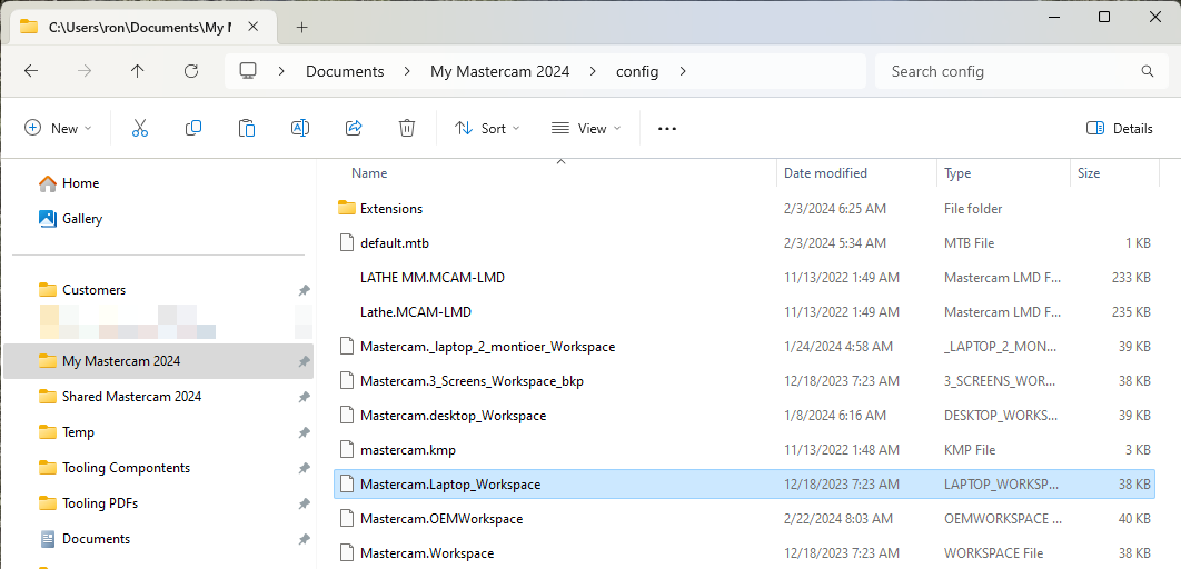
I have been doing a ton of traveling this year and have had many different screen setup to deal with. My home setup is (3) 27" Asus Monitors using a dell docking station. One the road I may have to mirror my laptop screen with a TV or monitor to teach Mastercam. Other places I have 2 monitors I can use. This can be changed each time and things moved around or I can just different workspace files. This is my current process by having backup copies of the different screen layouts and then just delete the current workspace file and then copy the one I need and rename back to mastercam.workspace I could write a BAT file to do this, but in less than a minutes I can make the change and so just do in all manually. HTH
 1 point
 -
Haas Z axis are notoriously unstable. I am running an UMC 750 and the spindle often grows 0.002 through the day.1 point


.thumb.jpg.e1ed32e8dc33a68b1f20806bb5d55e08.jpg)