.jpg.1d0c9069edb5ce000980cbe1b76f0865.jpg)
CEMENTHEAD
-
Posts
359 -
Joined
-
Last visited
-
Days Won
4
Content Type
Profiles
Forums
Downloads
Store
eMastercam Wiki
Blogs
Gallery
Events
Everything posted by CEMENTHEAD
-
something you can try. I just did it and it works. you have centerlines. create surface, draft, half your slot width, both sides. all centerlines change your color and use Silhouette Boundary. or surfaces to solids, boolean add all, add fillets change your color and use Silhouette Boundary.

-
.thumb.jpg.15afa8dbfcde0167893a4a297d335e0b.jpg)
Pitch in your little gems that make mcam life easier
CEMENTHEAD replied to jlw™'s topic in Industrial Forum
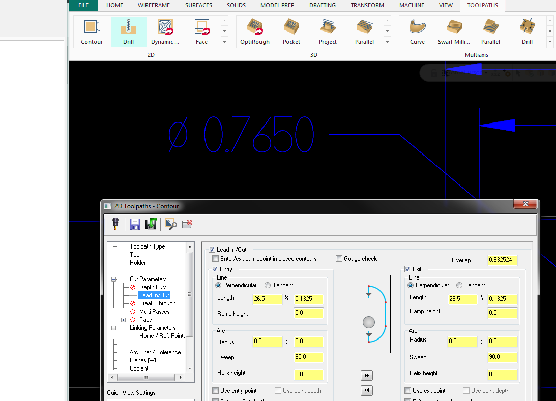
OK. Here is one I'm sure many of you do already. One of my guys asked "how do you do that?" today. PLUSES OF OVERLAP Thought everyone knew this one. hole DIA - tool DIA then multiply by Pi = circumference (length) of cutting-path. type all the math in the boxes (Boxes can math) This keeps a tool down inside a hole for as many revolutions (spring passes) as you want without coming off the part or retracting. here I'm cutting a Ø.765 with a Ø.500 EM, set your overlap to (Ø.765-Ø.500)*Pi = .8325 overlap 1 revolution (spring pass) OT I also use (Ø.765-Ø.500)/2 = that sets as my lead in at center. ( only cause i subtract the amount of stock allowed for multi passes or stock left. )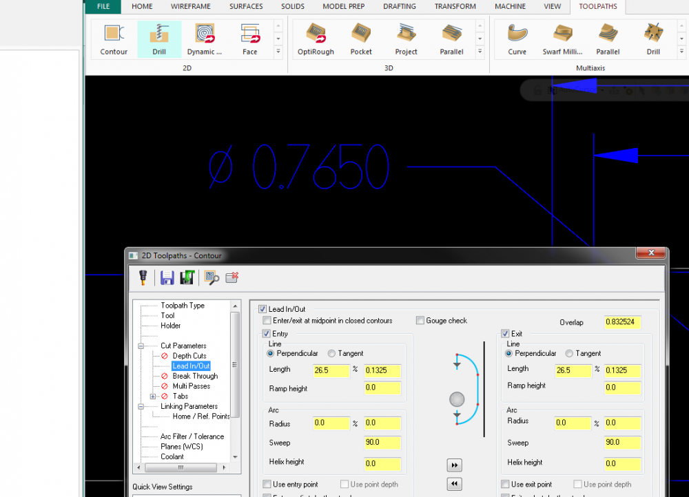
-
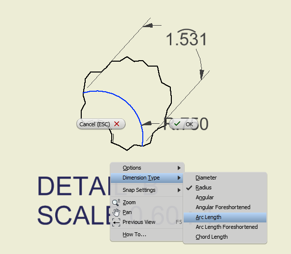
I honestly couldn't think of a reason for having it (length of arc dimension). The Rad is already given, R*Pi works. or F4 the length and Note (length between point "A" and "B") maybe cutting tape? In our Autodesk 2019 its called (arc length).
-
tru .. need to know the OUTS before you put the IN in.
-
At least AD Inventor doesn't rape you in to a licenced purchase agreement like (cough cough) pro E. oh xxxx.. too close to UMAss.. I mean "Force".
-
using the ".set" file TOOL LENGTH FROM HOLDER = ", *tl_overall_len, e$ FLUTE LENGTH = ", *tl_flute_len, e$
-
Drafting in MC is horrible, always has been, always will be. almost Unplayable. Straight from Tolland... "It's not drafting software"
-
We also have seats of AD Inventor and UGNX, when I hit a snag I'll open and convert it back in another software. In inventor it trees up all the bodies nicely. (grabbing only the main body and exporting as a step again.) If its not proprietary i'm sure someone here would be happy to help you separate it. I agree with the native "tolerance" issue prior to .step export.
-
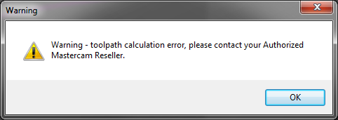
Anyone seen this? toolpath works fine in 2017, this error in 2018. Just a simple contour line 2d toolpath, projecting onto a radius. Weird. I can work around it. but strange.
-
Measuring inside groove diameter (Best tool for)
CEMENTHEAD replied to Roger's topic in Industrial Forum
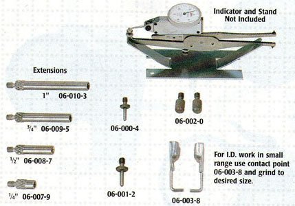
INDI-CAL INTERNAL GROOVE GAGE These are my groove diameter go-to -- there are all sorts of tips, and most of mine are ground to suit.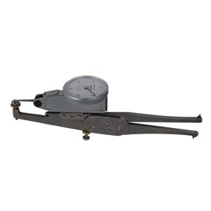
-
Yes, it's annoying at the least. Iv'e even had it seem to track the mouse 4" off, (highlight over empty space to see selections yellow up to the left) Weird, Zoom in and out it fixes itself. can not duplicate any of these, randomness
-
chopping carbide endmill shanks?
CEMENTHEAD replied to Matthew Hajicek - Singularity's topic in Industrial Forum
even buying a garbage wire edm just for this and other odd jobs is worth it. doesnt have to be a good one. we had a junker we used for weldon cutouts, trimming endmills, and splitting rings. used the xxxx out of it before the real estate it sat on was worth more that itself. -
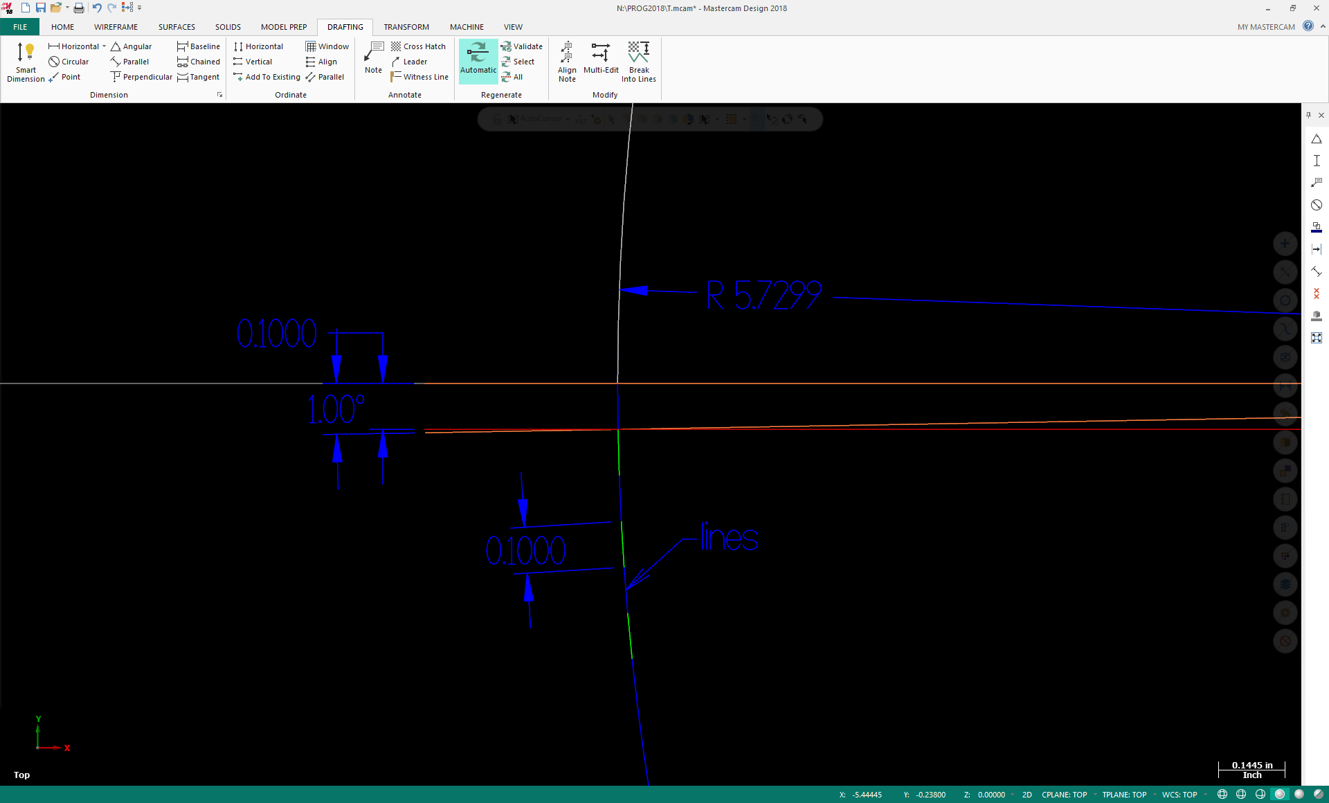
creating a horizontal line 10" long, rotate (copy) it from its endpoint +1 deg. offset the original down .100. Then create an arc from axis of rotation (endpoint of horiz line) to the intersection of the offset line to the rotated line. you get a Rad of R5.7299 which equals a .100 line length at 1° HTH
-
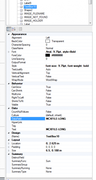
we used to use MCXFILE-LONG our filenames are our program numbers. gave up on the Active Designer setup sheets years ago when we first saw it. We stick with the .Set files. less paper
-
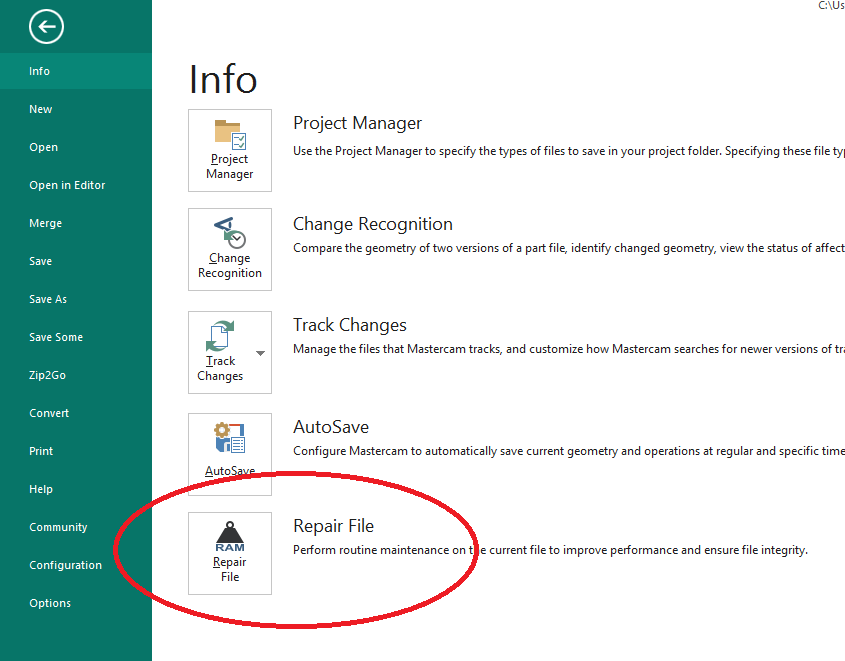
There used to be a feature called "RamSaver" It was moved to the "file" page and renamed to "repair file" Might help.
-
https://nraynaud.github.io/webgcode/ Used this once or twice. free
-
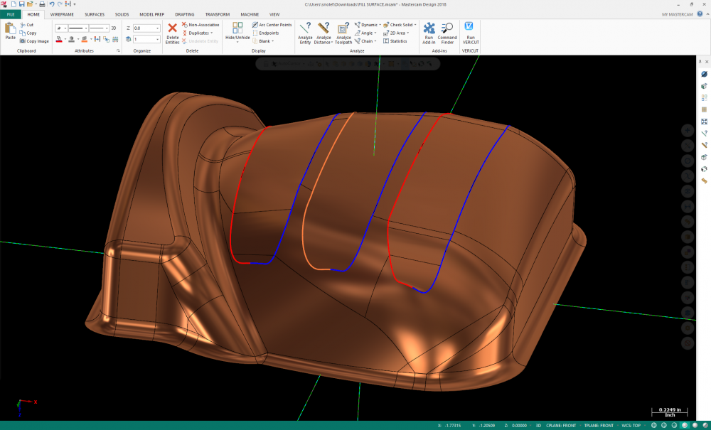
If the slot is going to be milled away, break it evenly, use loft/ruled surface. Doesn't look it, but it is smooth enough to surface.
-
could just draw it hatch it and save it. merge it in whenever you want it.
-
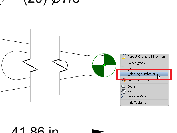
No. I'm Thinking he means the same as a "datum point" Circle with plus and two opposite pie shapes shaded.
-
Funny, they don't offer it until someone requests it. I normally have to hound them weekly 6 months after MC release. The interface turns a 40 min job of setting crap up into 3. definitely a MUST HAVE.
-
Set a tool plane to where the first cut (tooth) is squared up, add your 2d contour there, use transform toolpath (rotate) by toolplane to the pitch of the teeth from whichever plane looks down the center of your rotary.
- 1 reply
-
- 2
-

-

-
Check your colors as well make sure your system Origin isn't the same as the background. Iv'e seen people use some crazy background colors in my time. ( yes even red ) why red?? why would anyone ever use red as a background in MC.. facepalm....
-
couldn't imagine why, but if your trying to nest things on a rotary, nest it flat and "ROLL" it in transform.
-
thx, I did see them. Think we are going to try and cut up a few of these. https://www.mscdirect.com/product/details/42639898