Leaderboard


Popular Content
Showing content with the highest reputation since 04/26/2024 in Posts
-
You can record a keystroke macro and trigger it from a keyboard shortcut or custom mouse button. I have an mmo mouse I use for things like this. I think some non mmo still have the ability to do this as long as you have an extra button??
 4 points
 -
Having a single Stock Model, at the end of your process, means you single-thread the removal of stock, from start to finish. Because each subsequent operation is dependent on the removal of material from the previous operation, you're limited in the speed the operation can execute at. Jake gave three great suggestions on how to potentially solve this issue. Or, just hit regenerate, and go get a cup of coffee while you wait. If you pause the operation, you can also Right-Click and set the Processor Priority flag. I like to use "High". I've seen no difference between High and Real-Time, but High does seem to give a performance boost versus standard.4 points
-
I already tried some sample code output from Camplete for Joas's YBM and got the same Z overtravel when I set the Z offset high enough. I think Colin's idea of using a regular G43 first and then turning on G43.4 afterwards might be the way to go. My new shop is like my old shop and I'm trying to run parts that barely fit into the machine.3 points
-
Disregard..... After opening the license activation wizard and looking around, I saw the license "deactivation" option and deactivated the HLE license. Probably should have tried that before emailing my reseller or making this new topic Maybe this will help someone in the future with the same issue.2 points
-
Holy molee, I have always reacted with a Ctrl+Z, and it never works. I'll try to stop next time and pull them from the fire. Had to update my 3Dconnexion software to get it to work, it was running the keys too fast and it happened before the flyout was available. The new update added delays to macros, so I pulled it off. Thanks again for the help. Actually ALL the help your resources have been over the years, appreciate it!2 points
-
Nope and a method to add more than one group at a time with custom naming along with sequential controls. These have been suggestion and numbers assigned over the years and nothing yet. I did have a Chook I used a couple versions back, but it has not been updated so only works in 20212 points
-
Here's a link to another post about this topic: Here is another link to a benchmark testing thread so you can see how you stack up: Another link from MC Northwest on the topic: (the benchmark file download is on this page) https://mcamnw.com/how-to-optimize-your-pc-for-mastercam/ And one more link discussing computer specs for the heck of it: The biggest points: 1. loosen tolerance on the stock models if you can 2. use more stock models to spread the load 3. stock model regen is primarily a single thread process, which bottlenecks the regen times HTH2 points
-
Not necessarily a tool change. Just trying to avoid adding another tool to the magazine, as its almost full and this machine has a bunch of jobs on it that run pretty much constantly. I ended up just adding a 1/8" ball mill though.2 points
-
So, it is often the case that the starting position for a TCP move can gouge or completely violate the part, if you're starting a path that is "on the far side of the part", or if you're transitioning between one side of the part, to the other. With a "Dynamic Work Offset or Tilted Work Plane" pre-position move, you're essentially 1) activating a work offset, 2) rotating the table into the correct starting position, 3) calling DWO/RTDFO to "dynamically align the active rotary face (A/C or B/C table position)" to a coordinate system attached to the part, 4) moving into a safe "XY Position", 5) using G43 to preposition Z with Tool Length Offset active, so you're driving the XYZ Tool Tip Position in coordinates which relate to the feature or zero position on the part. In terms of looking at the code, using G68.2 makes it really easy to gauge position and approach/retract moves, with a WYSIWYG (what-you-see-is-what-you-get) approach. With TCP on a Table/Table setup, Ben mentioned, "X6.7 is really the Z-Axis". The XYZ Coordinates for TCP are output as if the vectors are related to the "part setup at Rotary Zero", which means just "reading the XYZ values with G43.4 active" is not as straightforward as it would first appear. The anecdotal evidence I've seen shows that "DWO/TWP Pre-Positioning" generally solves this issue, which is why it is featured as an option in most advanced Post Processors. In the ideal setup, you pre-position using DWO/TWP, position tool tip using G43 (TLO), cancel TLO with G49, then cancel DWO/TWP (G69), and then invoke G43.4 Hxx, and if you output the same XYZ starting positions (or not), then when the TCP moves start, you're already perfectly in position because of the pre-position moves, and the path essentially "always works", or at least you can catch issues and diagnose root cause, much more easily by observation during the pre-position process. On a Table/Table VMC machine, using TWP, you're essentially always rotating a plane on an angled face into alignment with the XYZ machine axes. This means in general that "Z = Z" once G68.2 is invoked, provided it is setup properly (machine parameters) and called properly (NC Code).2 points
-
I believe defining it as a T-slot cutter with corner radii will work.2 points
-
We have the 1053 delimit tool path setting on as a recommendation from Camplete. What this does is on 5 axis paths since there is no transition block it zero returns z and starts the next path, no tool change spindle keeps running. It doesn't affect 3plus2 because there is an approach block short that transitions to the next path. I did mess around with the multi axis linking in Camplete but for us it's not worth using.2 points
-
I just did an undercut fillet with a T-slot cutter the other day. I used Flowline, with Direction and Depth Limits, and it worked perfectly.2 points
-
Although my toolmaking apprenticeship, turned into Modelshop/R&D, that quickly turned into the DO at the age of 21. I was REALLY fortunate that my mentor agreed to take me under his wing - he told me "I don't think I can make a silk purse out of a sows ear, but I think I can make a sows ear purse out of you" But we'd hit it off early during my apprenticeship - while work experience in the DO, he gave me my 1st job which was to copy an existing print. Mylar, 5H and 2H pencils, rule ("we don't call them rulers in here as the Queen of England has F'all to do with this job") square, protractor, compass and the most important thing eraser - and away I went. The part was the base of an instrument which was square with the 4x corners turned off, and everything was about the C/L - and I thought I was doing okay when he said "that top right quadrant - tatty - have another go at it"....so the eraser got a hammering and 15 minutes later "that's good, but it shows up the bottom right quadrant - have another go at that"....so out with the eraser again and 15 minutes later rinse and repeat for the left hand side.... End of day I remember him saying "the cleaners will love you tonight - look at all that mess on the floor" But yes, printing was my downfall - CAD was a godsend. There's 2x real arts to being a drafty from a "picture drawing " perspective - neat printing, and the most important one having the initial visibility of first laying the job out in your head so you know you can then get all views and all dimensions on the sheet. As with everything now, things change and it's a lost art - but we now have the other extreme where "everyone can use a computer", so everyone thinks they can be an "engineer"!2 points
-
Back in high school we had an old German welding/ drafting teacher, much like G-Code describes (drill Sargent/ taskmaster). He would make students cry. I still remember everything he taught us (well I think I remember!!!). Yes drafting with a T-Square and Vellum paper! I had an employee retire after nearly 40 years, he didn't use computers.... he would make "quick sketches" (his description) that were nothing short of works of art. Everything neatly scaled, shaded and sectioned and dimensioned immaculately.2 points
-
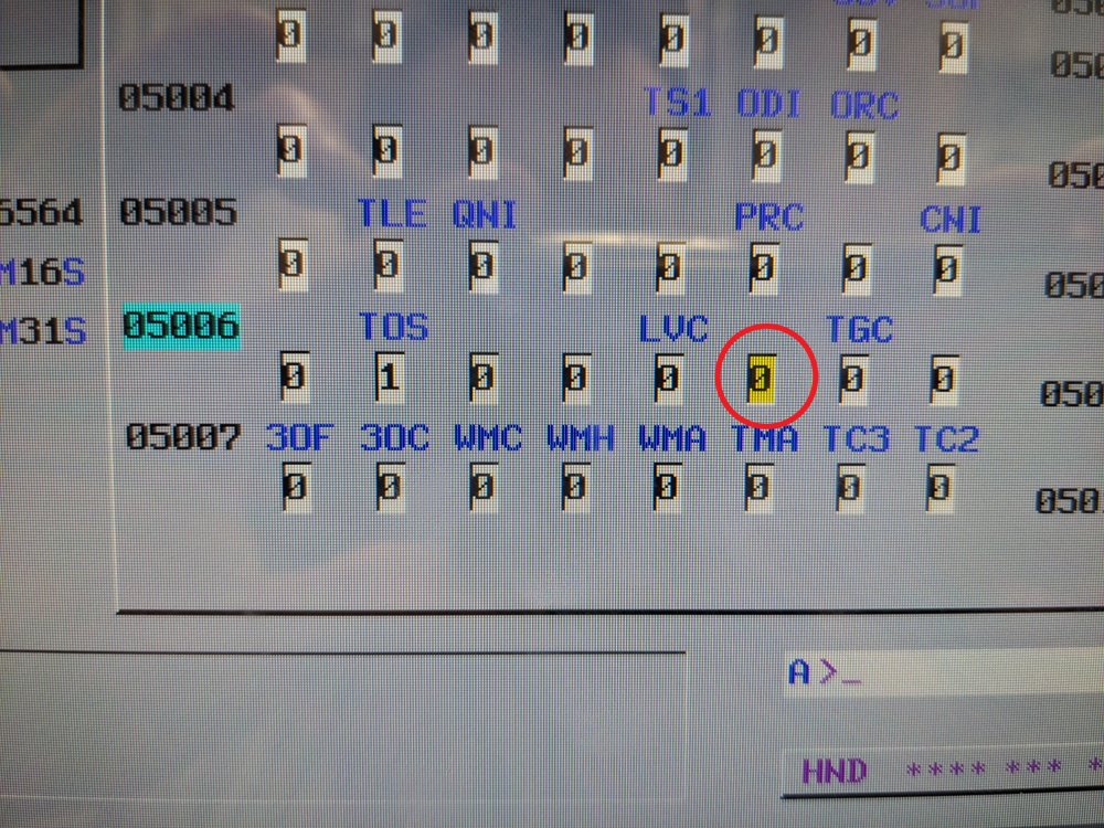
That's bit #2. Bit count moves from right to left, starting with zero. "TOS" is bit #6.2 points
-
I'd suggest the opposite > try adding all three values (XY & Z) on the G43.4 line. As an alternative, I would suggest having the Post modified to include a G43 Hxx Zxx line, inside the G68.2 call, to pre-position the Tool Tip, to the same position as where the start of the G43.4 toolpath move is. If you do this, be sure #5006.6 is set to prevent "motion on G49", and also that "G49 comes just before "G69", then you can invoke TCP. G54 G17 G90 G00 B-90. C-180. G68.2 X0. Y0. Z0. I90. J90. K0. G53.1 X-1.8735 Y3. S1000 M03 G43 H10 Z6.7 G49 G69 G05 P10000 G43.4 H10 X6.7 Y-1.8735 Z3. Z-.99445 X6.1 G01 X5.7 F25.2 points
-
That's a very cool solution, thanks for sharing1 point
-
I make them separate view sheets normally, but an automated way to output them not sure of one.1 point
-
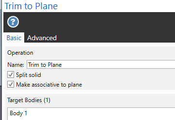
Trim to plane and split solid is checked. I normally uncheck Make associative to plane to not get issues when deleting un-needed plans in the planes manager. 5 seconds of work answer both of your questions?
 1 point
 -
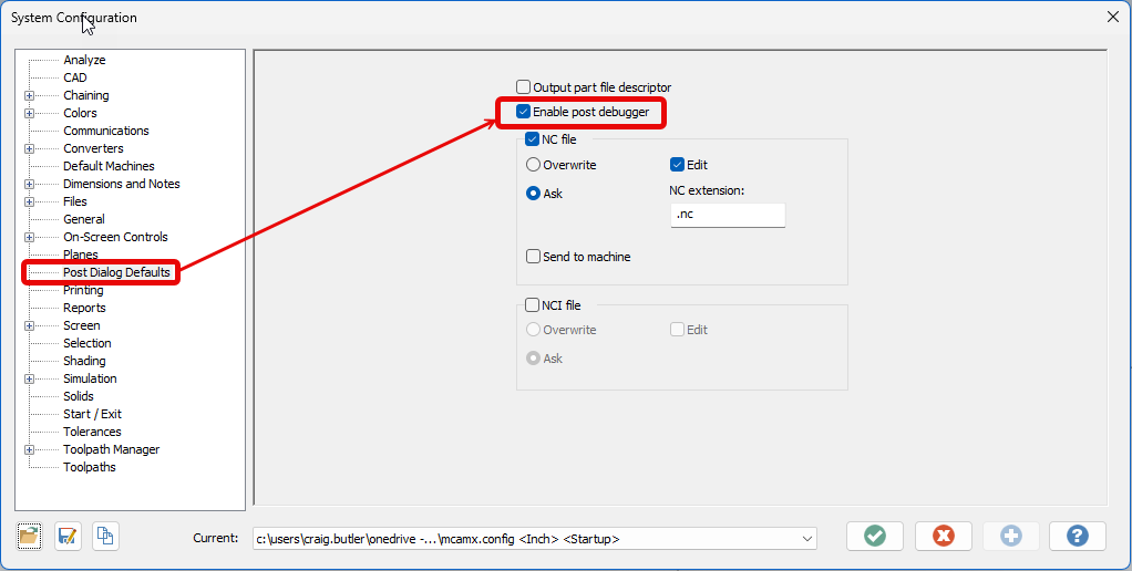
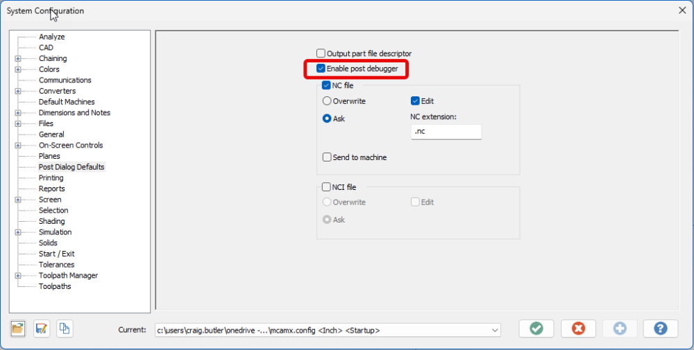
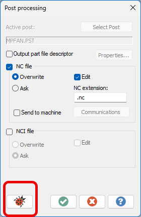
Yep, Post Debugger, and you need a Mastercam License to use/run this. Also, you can install and use Mastercam Code Expert, which has all the pre-defined variables and functions listed, using an "auto-complete" feature. By the way, if you're looking to learn about Post Processors, I have a free Post Processor Class (actually several) on my YouTube Channel. Link in my Signature. For MP 101 - Basic Post Processing, there are 28 videos. Be sure to watch all the Office Hours sessions as well. For MP 301 - 5-Axis Post Processing, there are 20 videos.1 point
-
Is One Drive running on your machine?1 point
-
that is usually in the locked section of the post. Nobody is goings to copy and paste it here.1 point
-
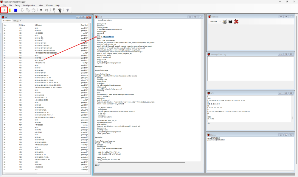
Hey Mavusi, They need to enable and use the post debugger. It will give you the ability to click on a G-code block in a .nc file and it will point you to the exact place in the .pst where that routine is defined. In the Mastercam configuration enable the post debugger. Instead of just posting run the debugger by selecting the bug When the debugger is launched press play run the file. In the NC window you will see the G-code if you double click the line of code it will show you where the code comes from in the post. Please note that if you have an encrypted post if will only show you the portion that is not encrypted.
 1 point
 -
If you are a legitimate user you can enter the site You have to register on a PC that has access to you Mastercam HASP or software license.1 point
-
What Crazy was suggesting is to mill the "floor" of that feature with a small tool and then come in with an endmill that has the .062" corner rads and plunge in to finish the walls/corner rads. I assume you're trying to avoid doing that to save a tool change?1 point
-
I have 2 Robofil 290 with automatic thread. Mastercam have 2 types of post for that machine. the first make a CMD file and several ISO files, and the second is a only ISO file. I use the second option. In the Tech Exchange page in Mastercam. com (HERE) you have those posts for free. But you will have to change some things to work well. You have to be registered of course:1 point
-
Note that your "TOS" Setting is already on! (That what we're confirming with #5006.6 being "on".) This means "no Z-Axis motion" with G49, which is the desired outcome.1 point
-
Thanks for clearing that up. Its been a while since I've had to mess with this stuff and I was vaguely remembering there being something weird about counting bits.1 point
-
Can I ask a dumb question here? Why not use a 1/8 stub flute ball endmill if you are worried about rigidity? Use the bull in the floor, but use a smaller tool. Why are you trying to use in essence a size on size tool for such a feature? Back up and approach this differently and you will reduce run time and improve the quality of the work. Really want to be trick get a .375 endmill with a .062R made on it and plunge in one shot dwell after roughing with a .005 smaller tool.1 point
-
1 point
-
That's awesome. I have only ran 3+2 jobs so far on the matsuuras so I have yet to feel the need to tackle this subject but this sounds like a great way to go about it. I do not mind a Z retract at all, but the M05 + M09 for no reason between toolpaths would probably be a little annoying if I was feeling O.C.D. haha Always a fun line to walk when trying to appease my O.C.D. and just let "good enough" be good enough. Usually how busy I feel dictates my decision.1 point
-
I can definitely see your point. I will stick to forced tool changes between multiaxis operations on the Matsuuras then For the Haas I have found some "workarounds" that seem to really smooth out the process. Main one being under "feed rate control" in a multiaxis toolpath I will have checked "custom feedrate for clearance blend spline" and "replace rapid with feedrate". and then under the multiaxis link settings I'll have it checked to output feedrates as well. I'll usually have them set around 50-100 inches per minute (with butt puckered and hand on the feed stop button) to first prove it out and if the motion is smooth out at the machine I'll up it to 200-250. Essentially this will force all of the multiaxis toolpaths to stay in TCPC during relinking (while in that operation) but during the actual multiaxis linking moves it does swap back to dynamic work offsets (haas g68.2) so I am still technically rolling the dice a bit. Now really thinking about it I'll probably stop using the multiaxis link on the haas just for standardization's sake though especially since eventually I'll be too busy to prove out every single multiaxis program. Appreciate the insight!1 point
-
Remember getting berated for using the eraser and not rolling the pencil well enough. I still have a drafting table, that thing is heavy!1 point
-
You guys are great- we are working on all the above. Thank you1 point
-
my drafting teacher made us memorize the factional tables from 0 to 1 by 1/64th We achieved that, then he demanded 1/128th. That knowledge really helped me in my early days as a up and coming machinist. I worked with a guy once who could do that in Mastercam V7 ( no solids) He would design and draft up B/P's for fixtures and tooling that looked like they came out of the Boeing engineering department.1 point
-
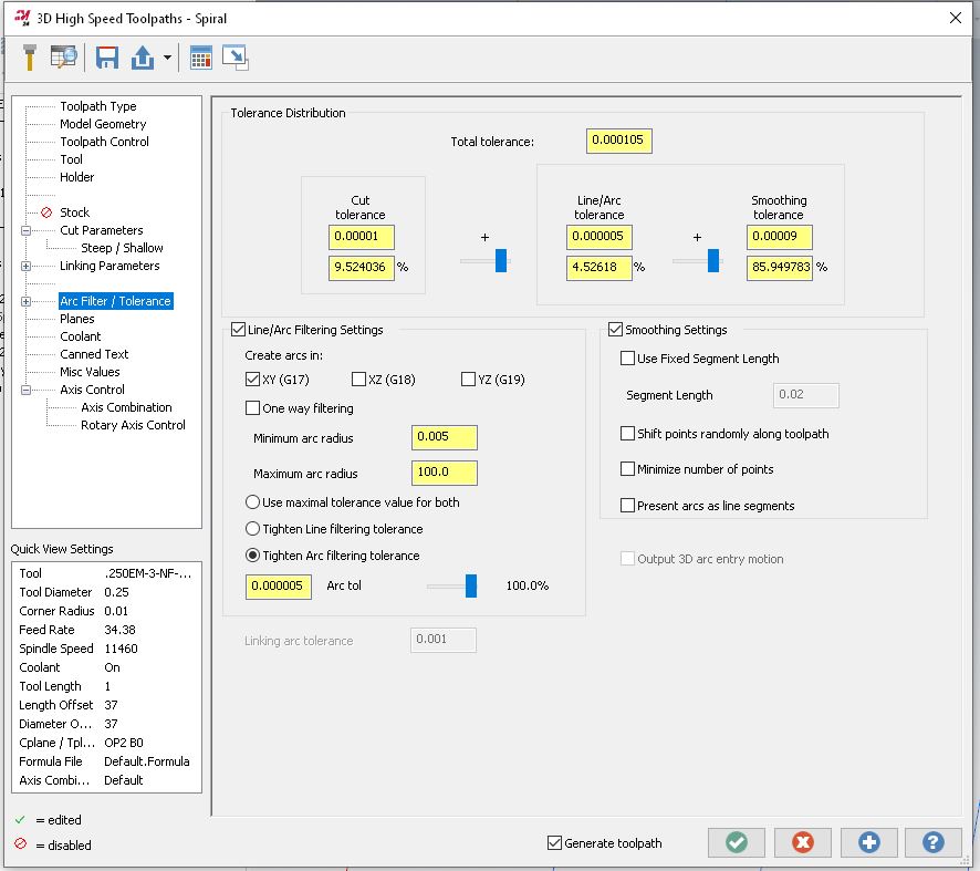
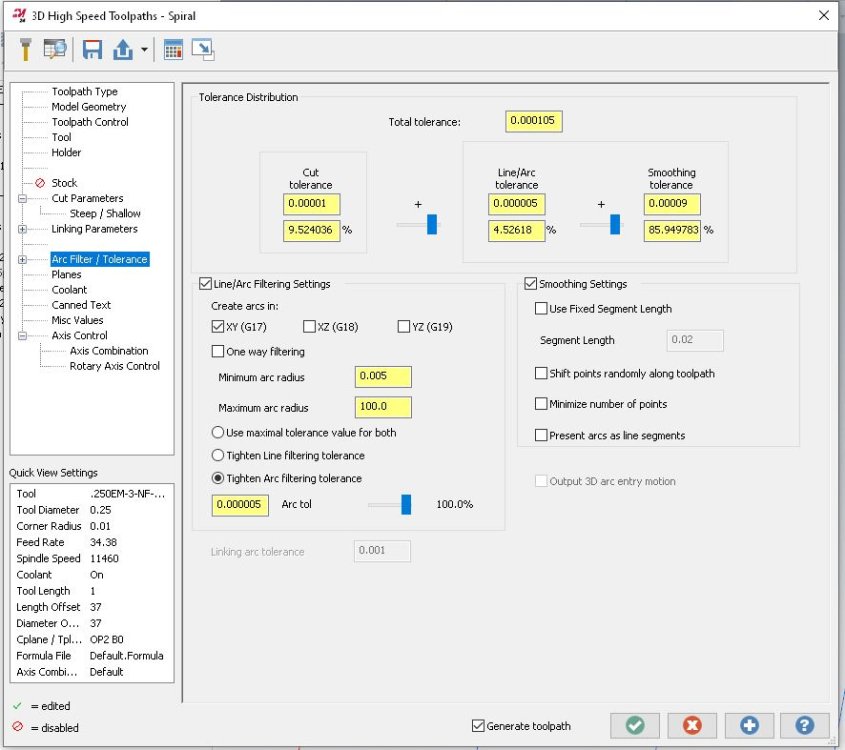
I changed the Arc Filter Settings and it seems better (took a while to generate though). Not sure how it will behave on the machine.
 1 point
 -
You missed the bit then where he said "Listen up G, in 53 years time you'll thank me for this NOW PAY ATTENTION"1 point
-
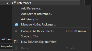
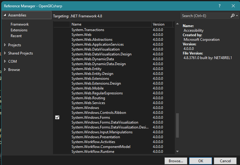
Yes, C++/CLI is the .NET Version of C++ that can be consumed at the c# level You can add a Winform to the C# Project by choosing add new item and choosing a new winform, you need to right click on references and click add reference and select System.Windows.Forms first1 point
-
Terry is trying to cut straight walls that are in the shadow of overhanging geometry. You ignore the overhanging geometry and develop a toolpath that cuts the desired straight walls only Then you create avoidance geometry to make the tool tilt and avoid the overhang It is not easy and it's a lot of work but it can be done. You would only go to all this trouble if you did not have a multiaxis license. This doesn't help Terry a bit because he has to build this part on a 3 axis machine.1 point
-
Flowline and Surface Finish Contour both support undercutting. Can you share a file?1 point
-
I tried adding all three values (XY & Z) on the G43.4 line but got weird undesired motion. I tried your second suggestion of using G43 inside the G68.2 call and that seemed to work. I tried it without changing the 5006 parameter and didn't get any Z motion with the G49. Is this the parameter I should change?
 1 point
 -
A bit of a shortcut in your method is that you can skip the "extend the two lines to their intersection point" when you create the circle. Just hit "i" key or AutoCursor > Intersection and choose the two lines, it'll snap to the intersection. ----------- You need 2 pieces of information to create a tangent arc. If you have those two pieces of information, you can calculate the missing 3rd, right? There's a critical piece of missing information to solving this, which is either the tangent point (on the bottom line) or the radius. Without specifying those two, there's an effectively infinite amount of possible answers. When you extend the bisecting angle lines, you're creating the restriction on the radius (1.50881301") so there's only one solution that fits the end point of the slanted line and the center point (Radius), which means you'll get a tangent point on the lower line at X0.57622467". Unfortunately, unless you have a specific reason for choosing the centerpoint you did (i.e., it's called out by the print to find the bisecting angle between these two features and create the radius centered off of that?) it's just really a random point in space that confirmation bias makes look more likely to be correct Note that Tom found the solution in solid works effectively the same way, using Constraints instead of the geometry.. If you use Mastercam's Arc Tangent > Arc One Point, you're now constraining two items: The end of the angled line and whatever tangent position is closest to that line. Mastercam will make an arc fitting with whatever radius you type into the panel. You can make a Arc Tangent > Arc Two Entities, which will do exactly what fillet would do, (in the background) it'll extend the angled line to the intersection and fit an arc of 1" (or whatever you specify). ----------- Basically, you're not asking the right question. For two lines of N angle, you can ask: What radius fits between these lines? Any of them, pretty much. What radius is a fillet? How many windows are in a house? If I give you a point and a line, what radius fits between those two? Any of 'em > the distance between the closest point to line. See above. If I give you a radius, where does that fit from this point to a tangent point on this line? THERE YOU GO! That's the right one ----------- I can't imagine that any CAD/CAM system can give you what you're asking for, as you're not giving complete information.1 point
-
Doing it in NX I also get Ø3.01761 point
-
Here's a video showing another workaround to get the arc I want. Dropbox - Create Arc Workaround Example1 point
-
What the pre-position does for you is create a safe and known transition from path to path. If you want sexy, YouTube worthy machine porn, there's a path in Mastercam (5-Axis Linking) or CAMplete's Auto-Link function (it requires an NC Format that supportsthe function. It has to be turned on also... by default it's off. If you want to know how to turn it on, let me know.1 point
-
X+ for Mastercam 2025 is ready. https://www.gmccs.de/downloads_x+.php1 point
-
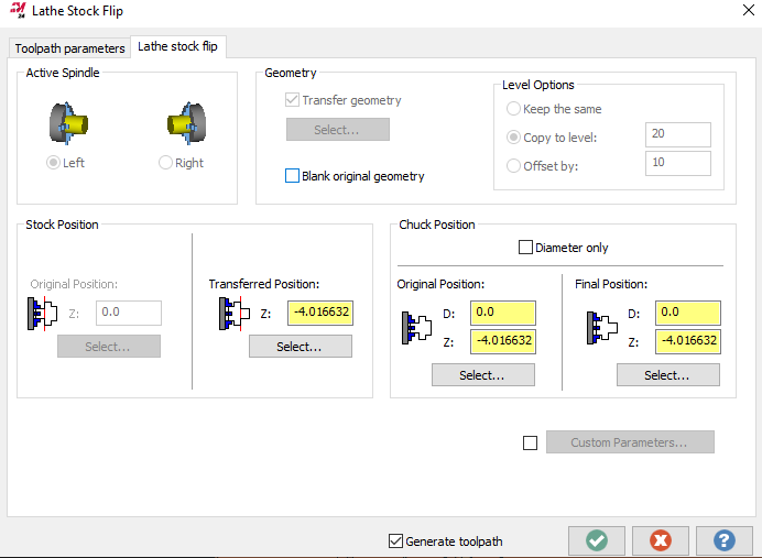
FOUND IT!!!! "Blank original geometry"
 1 point
 -
Axis Substitution requires a different method when trying to transform rotate. You need to use "Translate" not rotate and "Coordinate" not tool plane. Then on the next page use "Delta" for Method. Rotary Ø * pi / # of pattern instances1 point
-
Sure... Pickup phone, call reseller...hello, I would like to buy a post with these options and I'll send some sample code... That edit is no easy lift.1 point
-
As long as you understand what MockSim is and is not, what Vericut is and is not, what CAMplete is and is not you can make educated decisions about what fits your need. MockSim doe NOT check G-Code. Tied to a Postability post it is a good solution for most things. Again, it's not fully simulating ALL the motion in your machine like M-Codes, etc... Vericut... they simulate the actual G-Code that will run in your machine. As good as your control file and machine stuff is determines how good your simulation is. By and large it is the gold standard for simulation. You can create your own machines if you desire to learn or you can buy them from Vericut, or you can hire someone to build them for you. YOu have choices. Vericut is NOT an integrated post processing solution so you will need a post either from your CAM vendor or from ICAM, or somewhere else. CAMplete... they simulate the G-Code created from their posted code. You cannot import and edited code. CAMplete IS an integrated Post Processing solution that will simulate the factory G and M-Codes. You have almost as much control over your machine as you would in a Vericut machine. You have limited machine editing capability and you cannot create your own machines. That is not an anticipated feature. The machines are factory configured meaning Matsuura, Okuma, Kern, Mazak, Haas, etc... has given their blessing on the accuracy of the models, motion, and functionality. Because CAMplete is an intagrated Post Processing solution, you have control over the code. The NC Formats are user customizable. Typically a basic NC Format is given to the customer that will run the machine well. I've got a decade and a half's experience developing NC Formats and I've got highly tuned NC Formats that take advantage of the majority of the features and functions of the Matsuuras (since that95% of what I spend my time on) and I'm adding new stuff all the time based on customer requests. Knowing the tools, knowing their strengths, weaknesses and capabilites os the key to getting the best solution for you. For me, nothing beats CAMplete. For you, Postability and Vericut may be best, for someone else, MockSim will do the job. Know your tools.1 point