Leaderboard


Popular Content
Showing content with the highest reputation on 10/09/2020 in all areas
-
Here is my opinion on the two products, both Cimco probing and Productivity+ are excellent and powerful products. Cimco i thought was Super easy to learn, if you want to be able to pick it up and learn it very quickly and easily Cimco may be a better choice since prod+ is a bit more of a learning curve, but on the other hand we can do more with prod+ at this time, quite a bit more in fact. CIMCO probing wins when it comes to ease of use and ease of learning, productivity+ wins IMO for people that want max power and capabilities when it comes to Code output your gonna see some drastic differences as well, mastercam productivity+ code is typically more difficult to read, this is because cimco probing is using the onboard macros where prod+ will make its own. so the code output from Prod+ could be 10-100x larger in size than the code output from cimco probing, so cimco probing wins if your looking for simplicity of code, its going to be easier code for someone to look at and read coming out of cimco probing verses prod+. When it comes to customization, productivity plus wins in this area, with prod+ you get a productivity+ post processor configuration tool, which means you can fine tune your probing cycles, things like adjusting the protected move feedrate, 1 touch or 2 touch measurements, probe backoff distance, etc. can all be edited on the users end right through the productivity+ post processor utility. This is another reason why productivity+ is so powerful and the reason why the code is more extensive because we can control almost every aspect of how your probe moves on the machine and cimco is going to rely mostly on the onboard cycles loaded with the inspection+ macros. Those are my opinions for what they are worth. again they are both great products, its just a matter of what your needs may be and what you may like better.3 points
-
Inspection+ is using a different, less extensive calibration cycle than Productivity+. Keep in mind that compensation errors can be greater, especially when measuring off-angle components. I've used both extensively. There are advantages and disadvantages to each, but to go over a quick bullet point summary: CIMCO Probing handles 95% of probing applications, targeting the most common use cases for process control or workpiece setup, with basic GoTo loop options. CIMCO probing is not limited to Renishaw hardware. Initial integration time is vastly reduced because CIMCO probing leverages the macros already installed on the machine controller for probing, and does not require things like dedicating variable blocks, macro posting, and machine behavior edits that Productivity+ requires for similar functionality Because of the simplified nature of the CIMCO product, it cannot do the higher end stuff Productivity+ can, like create constructed features and advanced logic to branch off of. The top end power and flexibility in Productivity+ is to be able to easily build a process and logic tree programmatically, and there's nothing else that replicates that. The targeted use case you want probing for is going to tell you which of these products is a better fit.3 points
-
Only true if you haven't run the vector calibration cycle and if you don't use vectored probing cycles. We always do the vector calibration and use the vector cycles when appropriate.2 points
-
Typically, the Primary / Secondary names refer to the Rotary and Tilt Axes. Any of the two rotaries can be assigned "primary", and the other assigned "secondary". Really, this just comes down to the math calculations inside the Post Processor. I will always assign the rotary axis with "the most rotary travel", to the Primary. On that Gantry in your picture, the Primary should be "C" (Rotates about the Machine Z-Axis). The Secondary would be A or B, depending on: Which machine axis the rotary rotates about, and which Address Letter the Machine Tool Builder assigned to that particular axis. For example, Haas Machines always used to assign A and B to the Rotary Axis Addresses, even though they are not rotating about X and Y Axes. Once they developed the Haas UMC-750, they ran into problems with TCP working correctly, so they had to assign the standard ANSI Axis Designations to the Rotary Addresses. I would recommend asking your Reseller for a copy of the Generic Fanuc 5X Mill Post PDF File. This file covers the method of setting up the Post, and also describes how to use the Misc Integers and Real Numbers to control the Post output. I used this document as the "base" for a 5-Axis Post Class I taught. We took the Gen Fan 5X Mill Post, and configured it for a Trunnion Machine, and then took a copy of the same Post, and configured it for a Gantry Machine. I also showed how the "Unwind" function works, and how to use the Approach and Retract Vectors in combination with MI7 and MI8 to control the Post. You should be aware that the Generic Fanuc 5X Mill Post (by Default), is not setup to handle the "modern 5-Axis Machine Functions", which make setting up the machine easy. The Gen Fan 5X Mill Post is setup to output the "Pivot Point" of the CNC Machine, for a Gantry Mill. This means you must calculate (exactly) the Tool Gauge Length, and the Pivot Length of your 5-Axis Mill, and you must supply these two numbers accurately to the Post Processor, to get good 5-Axis Code. This is really the "Old School" method of running a 5-Axis machine, and it worked for many years with great success, but also has many pitfalls. Foremost, is the fact that you must accurately measure every tool, before you Post Process the NC Code. If you happen to have a Tool Offset Length that changes, then you must "re-post" the NC Code for that new tool length. For Gantries, the can lead to many issues, as you might have guessed. On a Gantry Machine without TCP or TWP (we'll get to those definitions in a minute), you are limited in the types of cuts you can do. Sure, you can do a full 5-Axis Swarf cut, relatively easily using Mastercam and an accurate tool length. However, you are limited to 3-Axis Compensation methods. This means you can only use standard TLO (G43/G44/G49), and you can only use Cutter Radius Compensation on the 3 orthogonal machine planes that exist on a Fanuc. (G17, G19, G18) If you have an "Angled hole", you must drill it point-to-point with G01 moves. You can't "tap a hole" on anything except the 3 Planes. To overcome this obstacle, they invented Tilted Work Planes. (TWP) This is G68.2 on a Fanuc Control. The TWP command allows you to do two things: Move the origin of the new plane, relative to the Current Work Offset Location. Tilt the "working plane" (G17), to new Rotary Angles. TWP allows you to use: G43 - Relative to this "tilted plane" G41/G42/G40 - Relative to this "tilted plane" Canned Drill Cycles - Tapping and Drilling on the Tilted Plane. You don't necessarily "have to move the XYZ origin", when using TWP. However, I think this is one of the great options of this feature. For example, I can give a new XYZ Origin, for the "face" of the plane I'm about to drill. This makes it so my Canned Drill Cycle Z Values are easy to understand. The "Z0." is now the tilted face of the part, so my Z Depth for the cycle could be something like Z-.855. If I want to drill the hole a little deeper, I can just modify the code easily at the machine. So much easier than a "R plane of 4.9226, and a Z Depth of 4.0721. (Example numbers, if I had not moved the XYZ origin with the G68.2 command.) Again, the Gen Fan 5X Mill Post is not setup for TWP or TCP or WSEC or DWO, by default. If you are familiar with the Post, and Post Editing, you can add these functions to the Gen Fan 5X Mill Post without too much trouble.2 points
-
Thank you! Finally that's the answer! All better now.2 points
-
2 points
-
We have to worry about stuff like this that is our job as programmers. I am called on to be the person in the know by a lot of companies and why I made the statement I did about not running the program the way I gave as the example. Another excellent point.1 point
-
Prod+ can be configured to output the "on machine" Probing Macros. You don't have to generate the full "Probing Macros", although you can, and you do have to if you want anything custom...1 point
-
If I understand what you're asking, it's about lubrication and wearing flat spots by the ball screw making many, many repeated small moves over the same area. This type of cutting is well-known to cause those kinds of issues under those circumstances....maybe not this week...but done enough, eventually...1 point
-
The Primary/Secondary designation also changes, depending on the Kinematics of the machine. Remember; a Trunnion rotates the Part, and a Gantry rotates the Tool. So between the two types; the calculations are reversed. There is a lot more to it of course. Reading that Generic Fanuc 5X Post PDF Guide might help you to understand the complexity that is built into the Post. There are so many different features to understand; how to set the default values, but also how to use the controls that are built into the Post to get the output you need. Ron alluded to this with talking about a "Right Angle Head". Although he used a 3rd Part Post Builder, the Generic Fanuc 5X Mill Post also has "Right Angle Head" options built into it. You can drive a RAH, mounted to a Gantry or to a Trunnion-Type machine, by using MI2$, the OAL Tool Length, and MI10$.1 point
-
On the Transitions Tab - Skip pockets smaller than is too large.1 point
-
Yes that is an example only. I assume no responsibility for this file being run on your equipment and any possible damage it may cause or create in doing so.1 point
-
Sorry on the my I mistyped that should be an mr. These are called Misc Integers and Reals that a post looks at in an machining operation in everything except MT. They are switches and they give direction to the post to do certain behaviors. Each post builder makes them their own and each one has very powerful functions depending on how the post is built. I have trained many programmers who have never once looked at them. They wonder why the machine goes home between each 5 Axis move. Yes you have told it to. No I didn't!!! Okay let me rephrase that. You didn't change the switch that controls that behavior and by default sending it home is safe. Change the switch that controls that and now you have told it not to and it will not. We get into old school Mill/Turn without MT and we have Lathe Switches and Mill Switches. Each has a specific function and if you not sure then go back to your post builder and get an expliantion of what, how, where and why they work. Keep asking question and keep learning all you can.1 point
-
We appear to have hit the parameter wheel lottery one of our new machines has this function. Has anyone done anything with it? In orbit mode the spindle becomes a w-axis and you put a lathe tool in it and it will synchronize spiral around apart to bore a hole or shaft. In synchro chip the C axis becomes spindle 2 with what appears to be a 33 RPM max rotation speed. So you can use it as a VTL or do the synchro chip with it1 point
-
Like Husker said not much different unless it is a limited Primary Axis of travel then it gets interesting. I have programmed many different bridge type machines and the stronger ones have a limited primary rotation axis. The weaker machines have a full travel primary rotation axis. What that means is you can spin it to infinity like a turn in type machine or even most 4 Axis machines. That means some times you may need to pre wind you head to do some large travels. The other issue is large parts may mean you have to dance around the part. Linking moves and understanding the mi and mr switches in the post that control home movements becomes important. The next thing will be risers if you need to machine at 90 degrees to your parts. Draw you a travel limit wireframes box so you can use it to help you visualize it when setting up your parts in your ,achi e space and what and here it will be on the machine. Next normal progression will be using a Right Angle head on your 5th Axis machining center. Don’t let it scare you and with the right post not to bad. Approach it like anything take the time to learn it get a good verification model and software.1 point
-
You just program it from wherever you want your zero to be. No need to visualize cor unless you need to worry about making a smooth resulting kinematic toolpath. Understanding the basic offsets of the kinematics of your machine help here.1 point
-
Download all the programs (including 8000's and 9000's) into a folder, then use Super Finder XT or similar to search within all of them for the strings "#8" and "#9". I use it to find programs that contain a certain tool.1 point
-
I've done this exact thing by generating slices along the centerline spline of the airfoil shape and then transforming the slice geometry to a flat plane representing the airfoil chord line of 2D profiles with relative LE offset to the centerline. The easy thing to start with is the defined section views of the airfoil off of the blueprint, which give you all your critical slice points. Die adjustments for twist and springback can then be dialed in at the sliced sections as planar angle adjustments, and the die surface re-swept through the adjusted wireframe. There are software packages that can probably do it faster, but I never used any specialized add-ins for this type of work, as the application differs from typical sheet metal spring calculations and there wasn't much out there claiming to be able to do this at the time.1 point
-
Most , if not all, of the full engineering systems have modules for various engineering categories (see Thad's example above). These tend to be very expensive so they try and break them up to keep the price somewhat under control.1 point
-
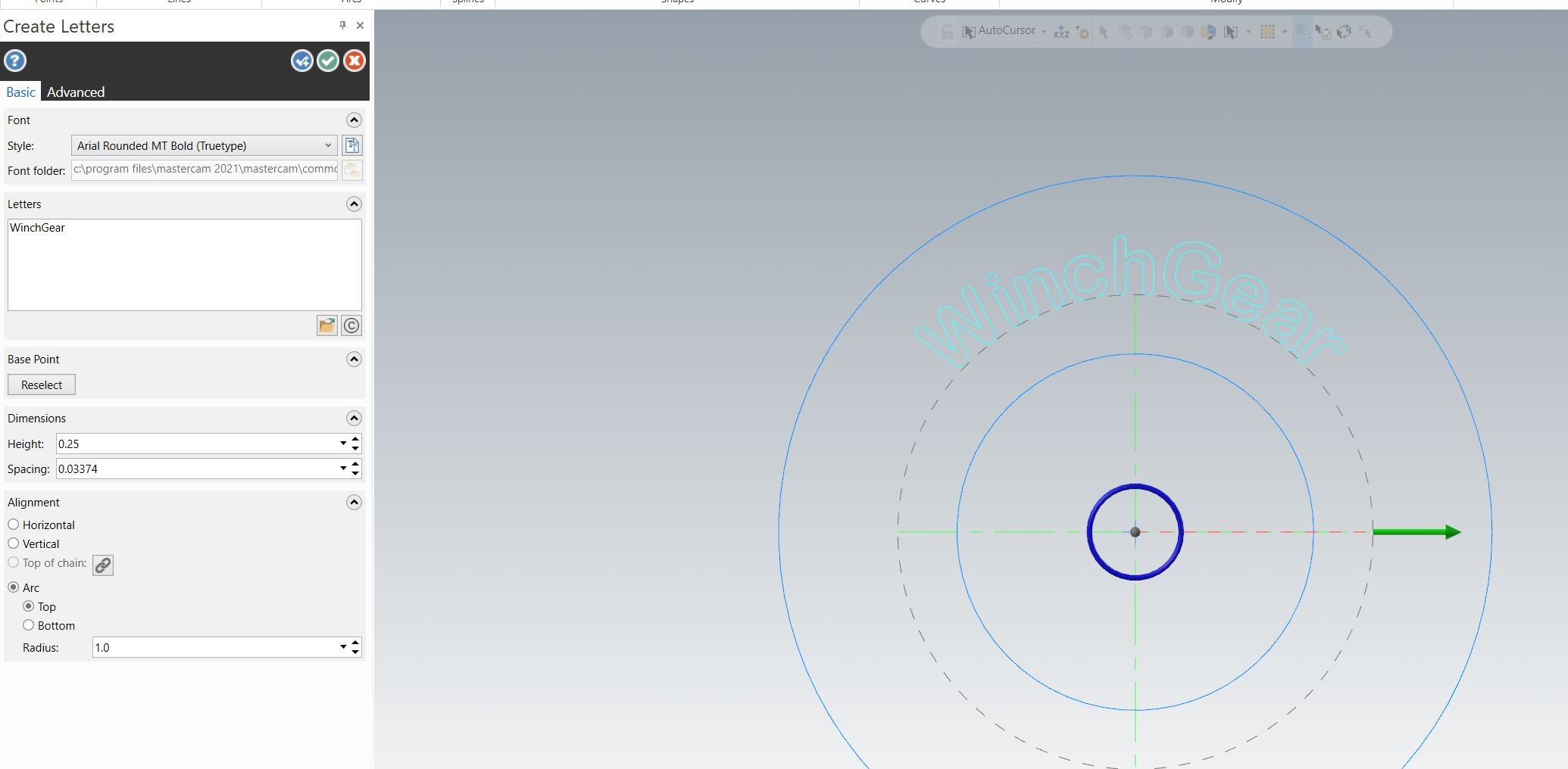
Here's your problem. Check None instead of Lines.
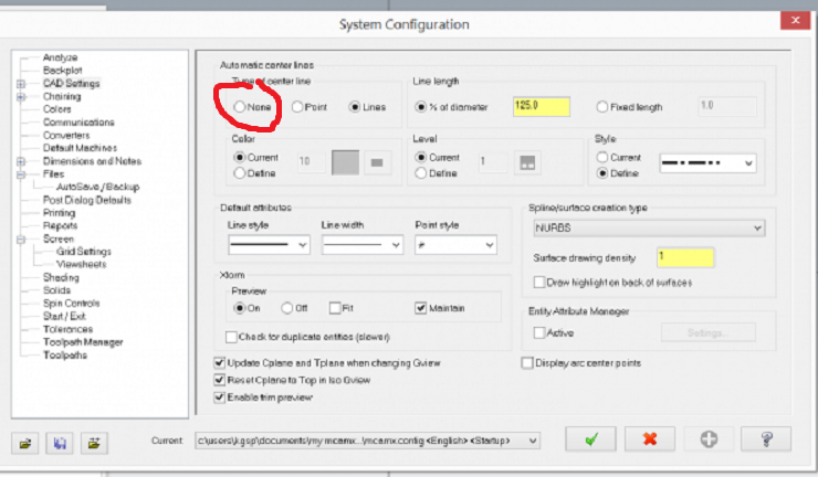 1 point
 -
Tap feedrates are ultimately a factor of the "Threads per inch", ie pitch The larger question is are you feeding tap in IPR or IPM? Using IPM..... If IPM say 500 RPM x .05" Pitch = feedrate = 25. If IPM say 800 RPM x .05" Pitch = feedrate = 40. If you change the speed, the feedrate needs to be adjusted Using IPR If IPR 500 RPM the feedrate is F.05 If IPR 800 RPM the feedrate is F.05 That is constant regardless of the speed change1 point
-
File > Configuration > Expand(+) Files > AutoSave/Backup1 point
-
Sort of like this?1 point
-
nah she will be fine, i'd let 'er rip, they make new ones every day but im the type of person that doesn't wear face masks driving down the highway so maybe im a rebel0 points
-
Right up in the corner...you don't have one?0 points