David Colin
-
Posts
791 -
Joined
-
Last visited
-
Days Won
10
Content Type
Profiles
Forums
Downloads
Store
eMastercam Wiki
Blogs
Gallery
Events
Everything posted by David Colin
-
5-axis Problem (that is driving me crazy)
David Colin replied to Kampfzentrum's topic in Industrial Forum
On your screenshot it looks like plane origin is associative to an entity. Try to uncheck 'Associative' before zero it. -
Backplot position forward-backward, where do I assign the keys?
David Colin replied to SlaveCam's topic in Industrial Forum
I have no idea but if you find a file, please share as I have the same issue... -
Backplot position forward-backward, where do I assign the keys?
David Colin replied to SlaveCam's topic in Industrial Forum
I think it's hard coded and not customizable. If you're using a localized release translator can have changed it... -
Upgrading from 2018 to 2019, lost right-click menu
David Colin replied to SlaveCam's topic in Industrial Forum
I have the same issue with my french localized release. If i use my workspace file with US release, all is OK except RMB context menu which restores to default. For now, i still wait for 2019 french release hoping i'll be able to migrate from 2018 as i could do it with 2017(French) -> 2018 (french). -
5-axis Problem (that is driving me crazy)
David Colin replied to Kampfzentrum's topic in Industrial Forum
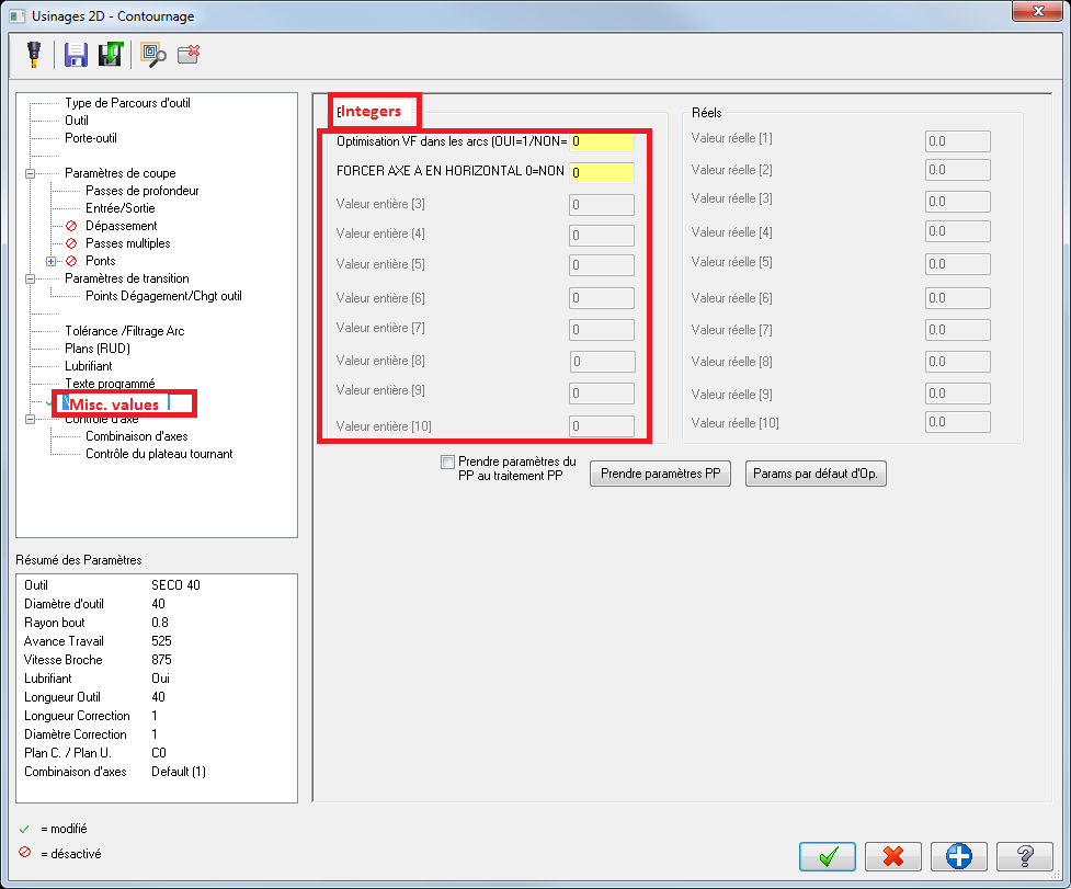
I was talking about this tab you can find in any toolpath. Depending machines/posts, values may be key in there. Then post reads them and acts accordingly with different behaviour. (sorry for french screenshot)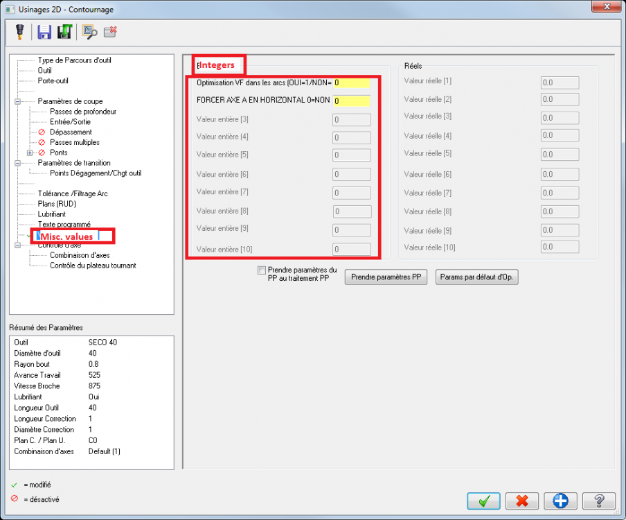
-
5-axis Problem (that is driving me crazy)
David Colin replied to Kampfzentrum's topic in Industrial Forum
Offsets are CD/post dependant. Did you check misc integers of toolpath ? -
Right clicking and select default sort usually get them back
-
Inverse time only posts minimum feedrate
David Colin replied to Matt Berube at Ferron Mold's topic in Industrial Forum
Because values are calculated like that: F(code) = 1 / (time = 3D distance/linear feedrate) With multiaxis toolpaths, distance between 2 points is usually very small, so time to move between these 2 points is small too. Logically: 1 / (small number) = big value -
Hi, here is an example with 5x curve projection. Download Mastercam file (2018) here
-
Do you want to save toolpath geometry (lines/arcs) ? If so in classic backplot window there is a button to save to a level. If you want to make a standalone part verify interactive file I think it's been implemented in 2018 and later.
-
Sure, but I m off this week. I ll try do it on monday.
-
I already had a nice result with multiaxis curve projection for this type of application
-
I think you even not need to click, just locate mouse pointer then type in values if you want.
-
I tried it once using ceramic buttons in Inconel and it worked OK. I only had a few parts to machine (diameter 380 lg50) so I can't say about tool life but there were no notch wear as it could happen with standard toolpaths.
-
Yes, except IMHO, dynamic gnomon performs even better than old rotate command if you're used to.
-
Machining Cloud by Smart Manufacturing
David Colin replied to [email protected]'s topic in Industrial Forum
Anyone still tried www.toolsunited.com ? -
MULTIPLE CUTTER COMPS....
David Colin replied to PcRobotic's topic in Post Processor Development Forum
It can be done but as already said, best is to split in 2 ops. (or ask CNC a switch to calc rough passes with computer comp only...) IMHO it can cause serious issues tweaking a post that way... you can count passes number set in Mastercam GUI but if CNC changes/improves routines in a future release (as it's been done in 2018 if I remember correctly) you probably will need to be careful (I ve already been bitten...) Another stuff to be aware: what if a user, one day, has great idea to post a toolpath with 'control' comp setting? It will make a crap part and a cutter broken...So don't forget to support that case in your post to output G41/G42. -
Yes, Just merge your saved verify .stl file as a mesh into your Mastercam part file, then move it where you need with any transform function (dynamic transform is my preference too) wa Here is a youtune video showing dynamic transform in action
-
I do like JParis on a Fanuc robodrill, binding user macro with a M code (M106)
-
I guess you would need to post something like : L M91 Y-1. Z-1. F MAX
-
Did you check your NC program (tool length compensation G code) and tool offset setting in Vericut tool manager?
-
This is usually straightforward, you just need to chain top and bottom wire path. Just pay attention to synchronization as any ruled surface creation. I guess you already got it but you also need a power Mastercam tech file for your machine definition.
-
This is a 5axis toolpath so it seems ok not to be able to get arcs here. You can get arcs only on standard planes (G17/G18/G19)
-
Threadmill Comp not working 2019
David Colin replied to [email protected]'s topic in Industrial Forum
I guess this is the same issue reported here : http://forum.mastercam.com/Topic27285.aspx -
Nethook in my signature can help with chains/points based toolpaths. If there are a lot of levels it should be faster than hide/show all levels process.