Leaderboard


Popular Content
Showing content with the highest reputation on 07/17/2020 in all areas
-
ok, here is an example file that shows axis subsitution on your file. sample part file - https://fastechincorporated-my.sharepoint.com/:u:/g/personal/support_fastechinc_net/ERaMd39pHRdCjdeVAFz-IhABs3NxwD8zKBxKj7OJB8yDXQ?e=KUgEyc video https://fastechincorporated-my.sharepoint.com/:v:/g/personal/support_fastechinc_net/EcvfKeRag0FCgeG9FDiICVUBMRE8vJPy06Oh-ETuDKqAiA?e=CtD6Lv if the video quality is poor in the browser you can download the video from that same link and if you download the .mp4 video it will play high quality EDIT: i just updated a new part file because i had that transform toolpath setup incorrectly, with axis subsitution we translate an axis subsitution path to get it to rotate like KB article 50169 shows. So please use this new link to the file since i have fixed the tranform toolpath2 points
-
Can I ask why someone would want to go about it this way? Best Practice for running programs on a machine is running the program for the part your making. Yes you can combine the Fixture or Jaw program in Mastercam into one Mastercam file I do it all the time, but to make it one NC Program is a disaster in the making for no reason. Scenario one you're new to this and setting up a part and half way through the fixture program you break a drill. You replace the drill and restart the program and now you ready to run the part. You start running the part and break another drill. You forget to restart in the old place and hit reset on the machine and start over. Now you have a crash and tear up your machine because that part is now where you didn't have it before making the fixture or jaws to hold it. Scenario two you have a long running part and it is break time and then you get called away to another job and it will be the next day before you can get back to the job. Machine was shut down and you come in and forget where you are in the program or cannot restart in that exact place and start over. Again another crash where you have your part in the place where you shouldn't because someone thought it was a good idea to combine the fixture to jaw program into one program. Ask the boss would you get new tires put on your car while your driving it down the road and think you also needed to get the oil changed? You do these in a logical order and no different with programs to make fixtures or jaws. They are one program and then your part programs is a different one.2 points
-
Totally agree. I disagree. I think subscription services where you lose your work when no longer paying are a scam. I also look forward to the next release. I've been included in several development studies and some of my input has been implemented in the software. I guess it depends on how you view the world but I'm going to put my best effort into any tool at my disposal.2 points
-
So I could be way off in the weeds here, but it sounds like you want to use the index position of the tool in the buffer as the diameter offset. Assuming that your buffer / tool list is non-repeating the below should work. First, I set up pwrtt$ so that a tool will only be added to the stack once no matter how many times it appears in the program. I much prefer then enhanced tool table for this, but since you mentioned pwrtt$... pwrtt$ if (t$ > 0) & (gcode$ <> 1003), [ p_add_to_tool_stack ] Next, I defined the stack and associated variables. stack_101_size : 0 stack_101_index : 0 stack_101_result : 0 stack_101_tool_number : 0 fstack 101 1 Then I created a utility postblock to add the tool to the stack p_add_to_tool_stack t$ = push(101, stack_101_result, 1) The below postblock will iterate through the stack looking for a matching tool number to the one passed in. If a match is found, it's index is set to diameter_offset and passed back by reference. If no match is found -99999 is passed back tool_number : 0 diameter_offset : 0 p_get_diameter_offset(tool_number, !diameter_offset) stack_101_index = 1 stack_101_size = pop(101, stack_101_result, 0) while stack_101_index <= stack_101_size, [ stack_101_tool_number = pop(101, stack_101_index, 5) if tool_number = stack_101_tool_number, [ diameter_offset = stack_101_index stack_101_size = -99999 ] else, diameter_offset = -99999 stack_101_index = stack_101_index + 1 ] To use this, at tool change (be it start-of-file, real, or null) do something like this psof$ ptlchg$ ptlchg0$ p_get_diameter_offset(t$, !result) That's it. If t$ exists in the list, it's index will be returned to result in this case. I hope that helps, but if not I'm sure someone more knowledgeable than I will step in.1 point
-
Leon82 we are doing this now. We use the standard G54, G55 work offsets for the toolpath groups so jaws or fixture are referenced this way (G54 Jaw program, G55 Fixture plate program). I asked whether we save jaws and fixtures and was told only with very complex parts. Years ago workholding was saved and storage space became extremely limited. This is the case in the last company I worked as well. Jaws are saved so repeat jobs can be more quickly setup. The racks of jaws however is constantly growing and very soon there will be no more storage space available. Here it was decided that making new soft jaws every time the job is run actually saves time and space. Tim see response above. It does make some sense to not store workholding indefinitely in inventory. As long as standard fixture plates and soft jaws are readily available, there's no sense in storing machined ones for who knows how long before they are needed again. I have some idea of what I can do. I will have to test out my theories. Thanks All.1 point
-
On the View Ribbon, "Appearance Section", click the little button in the lower right corner. Change your "Chord Height" to a lower number, for a smoother rendering of the tool. Also, check the "Curve Tolerance", "STL Tolerance", and "Workpiece Tolerance" Settings, inside the Simulator Options dialog. (Button next to "Verify" in the Toolpaths Manager.
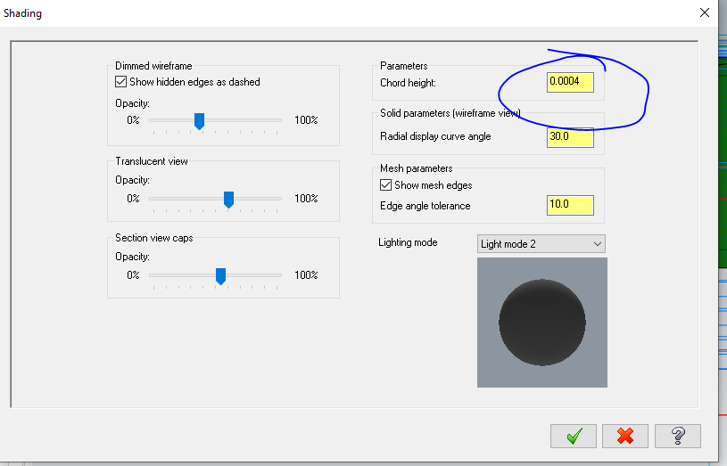
 1 point
 -
Multiaxis roughing is perfect for this application if you're using 5 axis.1 point
-
Have the post alter the variable 'speed' so a spindle speed not ending in zero won't happen, such as: change the least significant digit to zero. speed = (int(speed/10)) * 10 or define a new variable, say, alt_speed then a new postblock: pfixspeed # spindle speed to end in zero alt_speed = (int(speed/10)) * 10 speed = alt_speed *speed or pfixspeed # spindle speed to end in zero alt_speed = (int(speed/10)) * 10 *alt_speed then substitute pfixspeed where speed is output1 point
-
@Tim Johnson We've setup a couple of these posts in the past and its been a while so I may not be correct but I believe the posts were setup with 2 machine defs a mill one and a lathe one. You would do most of your programming within Mill and then then when you need to use this option you would load a lathe machine def in and program your toolpath within Lathe. I also believe this is an option and you may have to order at the time of purchasing the machine. But you might be able to get it added on after the fact. You would have to check with Okuma. Mazak has something similar called Mazak Orbiturn but I'm not sure how that cycle works and am pretty sure again this is an option on the Machine.1 point
-
We don't cut our fixtures every setup but why else would you to have both programs in one file? We had to re-cut casting fixtures a couple weeks ago because the castings over the years have grown to the large side edge of tolerance.1 point
-
Just organize the file system on your server. If op 2 gets a fixture it's program is op 2 fixture. How often do you have to cut fixtures though. If you're using soft jaws you should be able to machine them in a way where they can be loaded in the vise repeatedly. Flat fixtures should only need to be fly cut once they're bolted to the riser and machine table. Or if they're ground they should be able to repeat every time Do you have to make a fixture every time you run a part you're doing it wrong1 point
-
https://www.dropbox.com/scl/fi/q9eka835t64nsqyv4id5q/rizzo-milling-database.xlsx?dl=0&rlkey=150l7hdgk6cg7qxbt6z7n133j1 point
-
@Mark@dmg-mori .001" long length line segments or .001" chordal deviation segments on the 10" diameter? Speaking of tests, I ran a head to head test 840DI vs. a 30i-B on an impeller. Fastest I could get the 840DI to go was 20% slower than the FANUC. I tried everything. COMPCAD... everything. The whole friggin kitchen including the sink. Same program. Same tooling. Same everything. FANUC beat it hands down. So there's that. I'll post up a link for the program for anyone that wants to run it. Just tell me the kinematic you need (A/B, A/C, or B/C).1 point
-
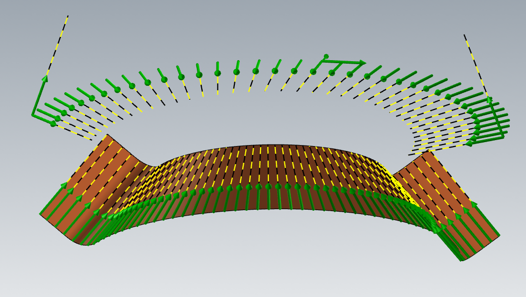
Creating Vectors lines for 5 Axis toolpaths. Use the Fence Surface to create a surface perpendicular to the surface your are wanting to drive from. Then use create curve flowline and see if U or V gives you lines that are perpendicular to the drive surface you want. Pick your line spacing and now you have perfect vectors to drive any 5 axis toolpath. I need to do a .005R x .005 deep Scribe line on a mold for a customer, but the problem was couldn't keep normal to all the surfaces it would crash, but then needed to be normal to other surfaces. I use this and some of my Jacobs ladder tricks and got a very nice toolpath to drive the part. The bottom row of vector lines is normal to the surface I am cutting and was created using the process described above. The top section is a Jacobs ladder process. I decided what my Center Vector would be and then what my end Vector would be. I then made mid section vector dividing that angle in half. I then drew a spline for the ID of the vectors and use the original arc for the contact area to the part. Now I use the create point segments to give me a equal number of points for each section. Then create line lock the auto cursor to point and draw from the contact surface out to make the vectors all go the direction I want. Now I can window select all vectors that are on a level by themselves and call it a day.
 1 point
 -
G28 burns you once....G53 for the rest of my life.1 point
-
You even can customize angle increment value in autocursor settings1 point
-
I generally place jaw/fixture program after M30 in part program.0 points
-
Haas UMC 750 and FTW.....0 points